Bolt Length Calculator & Grip Chart: Structural Bolts in Inches and mm
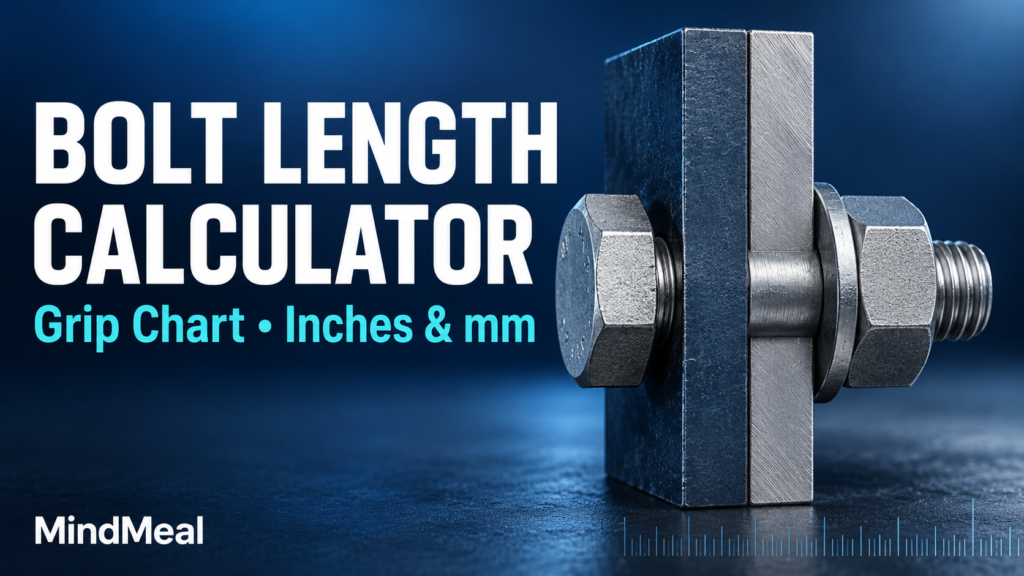
Use this Bolt Length Calculator & Grip Chart to estimate a nominal length for U.S. inch-series heavy-hex structural bolts. Add the thicknesses of the connected plies, select a bolt diameter, and include the applicable washer allowances. Results show both inches and millimeters.
The calculation uses the bolt-length allowances in RCSC’s June 5, 2025 specification, Commentary Table C-2.2. It estimates length only; it does not determine connection strength, required washer arrangements or installation acceptance.
Bolt length calculator
Scope: inch-series heavy-hex structural bolts and heavy-hex nuts. Not metric M-series bolts, tension-control assemblies or anchor rods.
Enter each connected plate, web or filler below. Fractions such as 3/8 and 1 1/4 are accepted. The unit selector converts existing dimensions.
Other hardware: enter its applicable total length allowance, not a count. Do not include hardware already counted as standard washers.
What does grip length mean?
Grip is the combined thickness of the connected material. For a shear tab bolted to a beam web, include the plate and web, plus any connected fillers. Do not include the bolt head, nut or washers in grip. Bolt length is measured from the underside of the head to the tip, so the head height is not added.
How to use the result
1. Enter every connected ply and select the inch-series bolt diameter. Use the actual specified material thicknesses, not a bolt-hole diameter or beam depth.
2. Select the standard washer count required by the project. The default of one washer is an example, not a universal installation requirement. Add a separate allowance for other applicable hardware.
3. Review the calculation breakdown and the preliminary nominal length. Confirm stock availability, nut engagement, thread position, tool access and the project’s adopted standard before ordering.
Calculation method and rounding
Calculated length = grip + standard-washer allowance + other-hardware allowance + diameter-based allowance.
Each standard ASTM F436 washer contributes 5/32 in (3.96875 mm) under this selection method. This is the prescribed calculation allowance, not a measurement of every washer. The diameter-based allowance already accounts for heavy-hex nut engagement and manufacturing tolerances; do not add the nut thickness a second time.
RCSC commentary describes adjustment to the nearest 1/4-in increment, or 1/2-in increment for lengths exceeding 6 in. This tool deliberately rounds upward to those increments so its preliminary length is never shorter than the calculated sum. That is a stated tool convention, not a claim that RCSC requires upward rounding. A longer bolt still needs a thread/runout and assembly check.
Diameter-based length allowance chart
| Bolt diameter (in) | Add to grip + hardware (in) | Allowance (mm) |
|---|---|---|
| 1/2 | 0.6875 | 17.462 |
| 5/8 | 0.875 | 22.225 |
| 3/4 | 1 | 25.400 |
| 7/8 | 1.125 | 28.575 |
| 1 | 1.25 | 31.750 |
| 1 1/8 | 1.5 | 38.100 |
| 1 1/4 | 1.625 | 41.275 |
| 1 3/8 | 1.75 | 44.450 |
| 1 1/2 | 1.875 | 47.625 |
Source: RCSC 2025 Commentary Table C-2.2. Metric values are converted from the inch values; a 3/4-in bolt is not an M20 bolt. This table gives a length-selection allowance, not a minimum grip or bolt capacity.
Example grip chart: 3/4-in bolt with one standard washer
| Grip (in) | Calculated length (in) | Tool-selected length (in) | Selected length (mm) |
|---|---|---|---|
| 0.5 | 1.65625 | 1.75 | 44.45 |
| 0.75 | 1.90625 | 2 | 50.80 |
| 1 | 2.15625 | 2.25 | 57.15 |
| 1.25 | 2.40625 | 2.5 | 63.50 |
| 1.5 | 2.65625 | 2.75 | 69.85 |
| 2 | 3.15625 | 3.25 | 82.55 |
These are illustrative results for one diameter and one washer configuration, using the upward-rounding rule. Change either input and the selection may change. The chart does not verify minimum grip, excluded-thread conditions or availability.
Worked example: shear plate and beam web
Assume a 3/8-in plate, a 1/4-in web, a 3/4-in heavy-hex bolt and one standard F436 washer. Grip = 0.375 + 0.250 = 0.625 in. Add 0.15625 in for the washer and 1.000 in from Table C-2.2. The calculated sum is 1.78125 in (45.24375 mm). This tool rounds upward to 2 in (50.8 mm). These thicknesses illustrate the arithmetic; they are not a connection design recommendation.
Checks the calculator does not replace
| Check | Why it remains necessary |
|---|---|
| Washer requirements | Hole type, installation method, bolt assembly and bearing surfaces affect the required arrangement. |
| Thread location and runout | A length estimate does not establish that threads are excluded from the shear plane or that the nut can tighten without interference. |
| Special hardware | Extra-thick, beveled, reaction and backup washers or direct tension indicators need their applicable allowances and arrangement. |
| Connection strength | Bolt shear, bearing, tearout, slip resistance and connected material checks are separate. |
| Product and project scope | Use the specified bolt/nut assembly, supplier information and adopted standard. Metric and tension-control assemblies require their own selection information. |
Frequently asked questions
Can I use mm? Yes, for thickness input and converted results. Changing units converts the entered dimensions. The selectable fasteners remain U.S. inch-series bolts.
Does a longer bolt always solve a fit problem? No. Nut travel, thread runout and shear-plane position may need review. Do not add washers simply to make an unsuitable assembly fit.
Does zero washers mean the joint is allowed without washers? No. It only changes the length arithmetic. The designer and governing installation requirements determine the washer configuration.
Reference basis
Research Council on Structural Connections, Specification for Structural Joints Using High-Strength Bolts, June 5, 2025: Commentary to Section 2.7 and Table C-2.2 (printed page 16.2-17). Use the project-adopted edition and applicable corrections. This article and calculator are a preliminary length-selection aid, not an approved fabrication or installation instruction.
MindCore