Double-Angle Shear Connections in Structural Steel
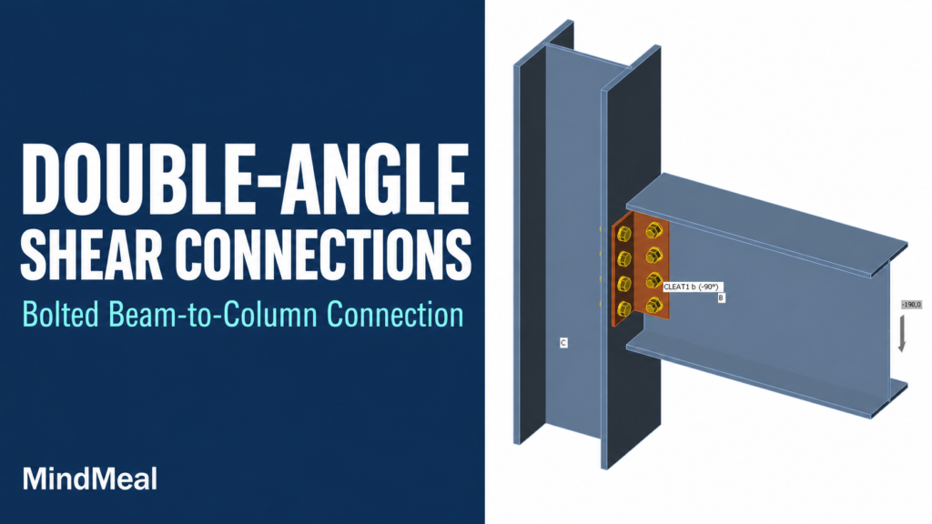
A double-angle connection uses two L-shaped steel angles, one on each side of a beam web, to connect the beam to a supporting member. One leg of each angle connects to the beam web; the other connects to the support. In a simple shear application, the assembly transfers the beam-end reaction while accommodating the required end rotation.
This guide explains the all-bolted arrangement, common welded variations and the drawing checks that distinguish a workable detail from a misleading connection sketch. The terminology follows U.S. AISC practice.
What does “double angle” mean?
It means a pair of angle sections, not two rows of bolts in a flat plate. The angles typically extend vertically along the beam web. A plan section shows their L-shaped legs clearly, while a beam elevation shows their vertical length and bolt rows. Both views are useful when reviewing a detail.
| Part | Purpose | Drawing check |
|---|---|---|
| Two beam-side legs | Connect the angles to opposite faces of the beam web | Angle orientation, web thickness, holes and bolt grip |
| Two outstanding legs | Connect the angle pair to the supporting member | Support-side bolt lines or the specified welds |
| Beam-side bolts | In the illustrated arrangement, pass through angle–web–angle | Bolt length, threads, washers and installation access |
| Supporting member | Receives the connection forces | Column flange/web or girder-web geometry and local strength |
How the load travels through the connection
For the illustrated all-bolted arrangement, trace the beam reaction through the beam web, the beam-side bolts, the two angles, the support-side bolts and then the column flange. In a balanced symmetric model, the two angles share the reaction. Actual design must remain consistent with the connection geometry and force distribution.
A bolt passing through angle–web–angle has two potential shear planes at those interfaces. That does not make the entire connection twice as strong as a single-angle or single-plate connection. The beam web, angle material, support-side attachment or supporting member may control first.
All-bolted and welded variations
| Arrangement | Beam side | Support side | Practical distinction |
|---|---|---|---|
| All bolted | Bolts through the two angles and web | Bolts through each outstanding leg and support | Requires access for bolts, nuts and installation tools at both interfaces |
| Shop-welded angles, field-bolted support | Angles welded to the beam web | Outstanding legs bolted to support | Beam-side bolt grip no longer applies; weld layout and fabrication sequence matter |
| Other designed welded arrangements | As shown by the approved detail | May use welds instead of bolts | Use the matching design method and weld arrangement; do not substitute attachments by appearance |
A double-angle detail does not always follow the same fabrication sequence as a shear tab welded to a column. Identify the shop and field attachments from the actual drawing. Do not assume that every line touching another steel part represents a weld.
Why a simple connection still needs flexibility
A beam end rotates as the beam deflects. A simple shear connection must accommodate that movement consistently with the structural analysis. Angle-leg deformation can contribute to this behavior; the connection is not an ideal frictionless hinge, even when the frame model treats it as simple.
Making the angles thicker, adding welds or restraining additional edges changes stiffness as well as strength. More steel is therefore not automatically a better detail. AISC connection guidance specifically addresses flexibility in double-angle simple shear connections. Keep the specified leg geometry and attachment arrangement unless a revised design supports the change.
Double-angle connection versus shear tab
| Feature | Double-angle shear connection | Single-plate shear tab |
|---|---|---|
| Connecting pieces | Two L-shaped angles | One projecting plate |
| Position at beam web | One angle on each side | Plate typically on one side |
| Common beam-side attachment | Through-bolts across angle–web–angle, or designed welds | Bolts through plate and web |
| Common support attachment | Bolted outstanding legs or a designed welded arrangement | Plate welded to the support |
| Coordination focus | Two angles, multiple attachment lines and access on both sides | Plate projection, weld line, beam setback and bolt access |
Both can serve simple shear applications. Selection depends on the reaction, support geometry, erection sequence, access and fabrication preferences. Neither connection type is universally stronger or cheaper. Avoid selecting one from a photograph without reviewing its design assumptions.
What the designer checks
| Check | What can govern |
|---|---|
| Bolts and load distribution | Bolt shear and applicable eccentricity or other force effects |
| Bearing and tearout | Material around holes in the angles, beam web and supporting member |
| Connecting elements | Shear yielding, rupture, block shear and other applicable angle checks |
| Welded attachments | Weld strength, connected base metal and the specified weld arrangement |
| Beam end | Net section, cope-related behavior and available web strength where applicable |
| Supporting member | Local strength and deformation at the connection |
| Rotation and fit | Compatibility with the assumed simple connection and room for assembly |
The AISC 16th Edition Manual reorganized the all-bolted double-angle design aids into Table 10-1a for angle strength, Table 10-1b for shear transfer at bolt holes and Table 10-1c for coped beam-web shear strength. The separate tables help make the individual checks visible. A value from one table is not a complete connection approval; read its scope, notes and companion checks.
A practical drafting review: seven checks
1. Confirm the design basis. Match the connection mark to the reaction schedule. Establish whether loads are LRFD or ASD and whether any axial or other forces are also specified.
2. Confirm two angles and their orientation. Show both angles in the appropriate view. If the legs are unequal, identify which leg connects to the beam and which connects to the support. Do not infer this from the symbol 2L alone.
3. Coordinate both bolt patterns. Check beam-side and support-side rows, gages, edge distances, hole types and slot directions. They describe different interfaces and need not be the same pattern.
4. Check grip at each interface. A beam-side through-bolt crosses two angle thicknesses plus the web and any fillers. A support-side bolt crosses its angle leg and the support, plus applicable fillers. Washers are added separately when selecting length.
5. Check beam setback and access. Show the specified end clearance. Verify interference with beam flanges, root fillets and adjacent steel, and leave room for bolt insertion and the installation tool.
6. Coordinate any cope. Where supported and supporting members interfere, resolve the actual geometry and required cope checks. Do not trim a flange simply to make a generic detail fit.
7. Reconcile plan, section and schedule. Compare angle size, vertical length, material, attachment type and bolt notes across all views. A clear section can expose a missing second angle or an inaccessible support bolt.
Reading a bolt-grip stack
For an illustrative all-bolted beam-side stack, assume each angle is 1/4 in thick and the beam web is 3/8 in thick. The connected-material grip is 1/4 + 3/8 + 1/4 = 7/8 in (22.225 mm), excluding washers. This arithmetic describes the stack only; it does not select the bolt diameter, length or connection capacity.
Keep this distinction when reviewing a bolt list: the support-side bolt has a different stack. Reusing the beam-side length at every location can produce an unsuitable assembly even when the bolt diameters match.
Frequently asked questions
Is this a moment connection?
The web-angle detail discussed here is a simple shear connection. A connection intended to transfer frame moment needs the appropriate force path, stiffness and design. Two angles alone do not establish a moment-resisting detail.
Should the beam flanges be welded directly to the column?
That is not part of the illustrated simple double-angle detail. Other engineered connection types may deliberately include flange welds. Follow the correct detail for the intended behavior rather than adding or removing welds independently.
Can the second angle be omitted if access is difficult?
Not as a drafting substitution. Removing an angle changes the force path, bolt shear interfaces and connection behavior; it requires a different verified design.
Reference basis
AISC Steel Construction Manual, 16th Edition, Part 10: Design of Simple Shear Connections; ANSI/AISC 360-22, Specification for Structural Steel Buildings; and AISC Engineering FAQs, Connections. The table organization is also explained in AISC’s “Key Changes in the AISC 16th Ed. Manual and 2022 Specification” presentation, February 26, 2026.
Use the project-adopted editions and applicable corrections. The original diagram and grip example are explanatory aids, not a dimensioned fabrication detail or a connection capacity calculation.
MindCore