End-Plate Steel Connections: How They Work and Where They Are Used
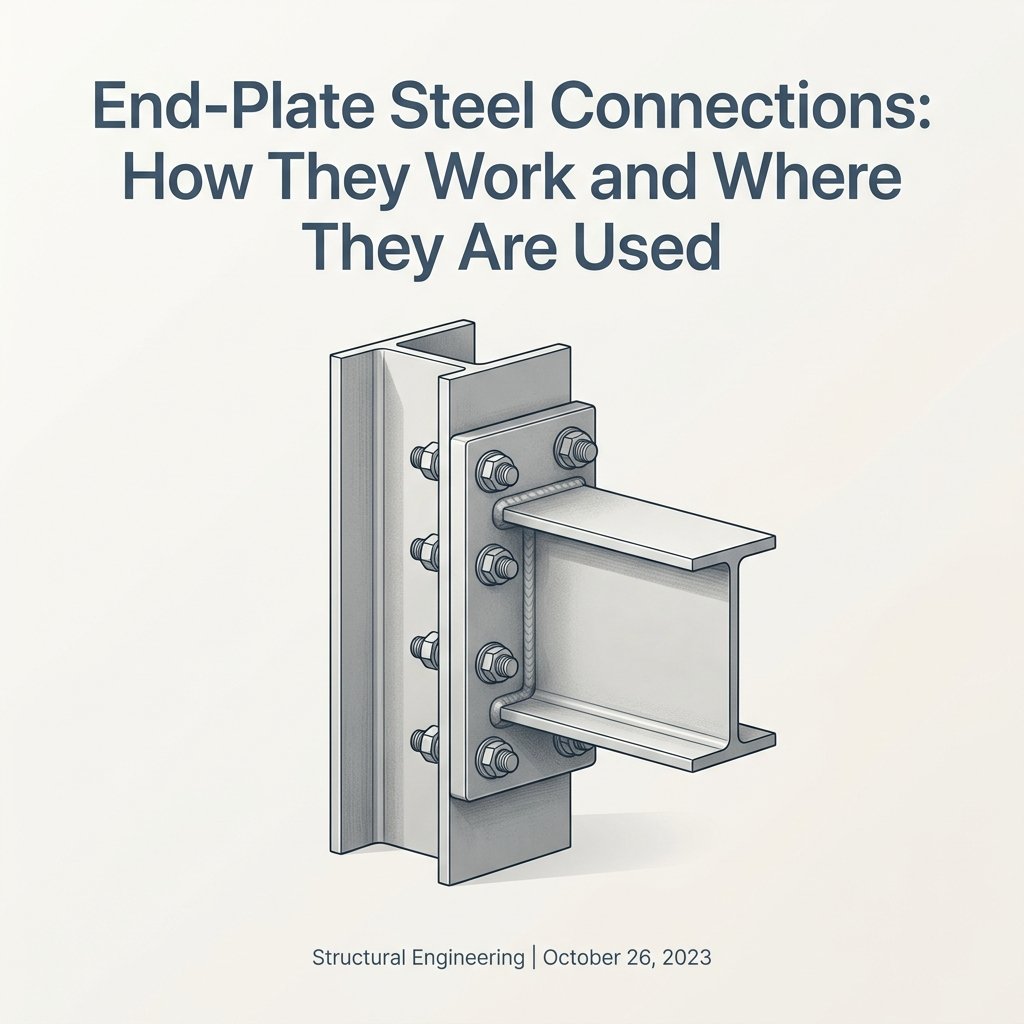
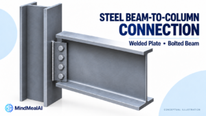
An end-plate connection places a steel plate across the end of a beam. In a common beam-to-column arrangement, the plate is welded to the beam in the shop and bolted to the column flange during erection. The name describes the connection’s arrangement; it does not, by itself, tell you whether the joint is intended to transfer mainly shear or significant bending moment.
For a drafter, the first question is therefore not “How thick is the plate?” It is “What forces and rotation must this connection accommodate?” That answer determines which parts of the beam connect to the plate, where the bolts go, and what supporting-column checks are needed.
Where are the welds and bolts?
For the arrangement discussed here, the end plate belongs to the beam assembly. The beam terminates at the plate; the plate bolts to the face of a wide-flange column flange. The beam does not pass through the plate. This is a different arrangement from a shear tab welded to the column and bolted through the beam web.
| Component or interface | Typical connection in this article | Drawing implication |
|---|---|---|
| Beam to end plate | Shop welding | Identify the beam surfaces being welded and show the required weld information. |
| End plate to column flange | Field bolting | Coordinate plate holes with holes through the column flange. |
| Beam flange to column flange | No direct weld in the illustrated end-plate arrangement | The end plate is between the beam end and support face. |
| Other supporting sections | Requires its own connection detail | Do not substitute an HSS face or column web for a column flange without checking access and local behavior. |
Shear end plates and moment end plates
| Feature | Simple shear end plate | Moment end plate |
|---|---|---|
| Primary purpose | Transfer beam-end shear while accommodating the intended beam rotation | Transfer moment and shear, and axial force if required |
| Typical beam attachment | A partial-depth plate welded to the web is one common arrangement | Beam flanges and web connect to the plate with designed welds |
| Plate shape | May be partial depth or full depth, depending on the detail | May be flush with the beam depth or extend beyond a flange |
| Key distinction | The detail must support the simple-connection assumption | Strength and rotational behavior must match the frame analysis |
| What appearance cannot prove | A full-depth plate is not automatically a moment joint | An extended plate is not automatically a qualified seismic joint |
Flexible end plates can be partial depth or full depth. The intended behavior depends on the complete detail, not plate height alone. The SCI/BCSA guidance describes these arrangements in a UK design context; its numerical rules should not be mixed with an AISC design. [1]
How the forces travel
Shear connection
For the partial-depth arrangement shown, beam-web shear passes through the web-to-plate welds, through the plate, and into the supporting member through the bolted interface. Connection deformation must remain compatible with the intended beam-end rotation. Adding flange welds, stiffeners, or a much thicker plate can change that behavior; those are engineering changes rather than drawing cleanup.
Moment connection
Bending is transferred through a tension-and-compression couple. On the tension side, the beam flange loads the plate, which loads the tension bolts and supporting column. On the compression side, forces pass through the plate into the support by bearing. The web and bolted interface also participate in shear transfer. If moment reverses, the tension and compression sides can reverse. [2]
A helpful equilibrium sketch is M ≈ F × z, where z is the lever arm between the force resultants. For an illustrative moment of 100 kN·m and a 0.50 m lever arm, F ≈ 200 kN. This is a force-couple illustration—not the demand on each bolt. Bolt-row distribution, plate deformation, prying, shear, and axial force still require a connection design.
Flush versus extended end plates
A flush plate stays approximately within the beam depth. An extended plate projects beyond one or both flanges, allowing additional bolt locations outside the beam depth. These terms describe geometry. The design must still establish resistance, stiffness, deformation capacity, and the behavior of the supporting member. [2]
Do not decide that a flush detail is pinned or an extended detail is fully rigid from its outline alone. Read the connection schedule, design forces, and applicable calculation. If the analysis assumption is missing, flag it before completing the detail.
Why plate thickness alone does not solve the connection
Plate bending can create prying action: contact reactions associated with plate deformation can increase bolt tension. A larger bolt or thicker plate may alter the governing behavior instead of resolving every limit state. AISC’s Design Guide 39 training distinguishes gravity/wind behavior from the intended beam-hinging behavior of seismic moment-frame applications. [3]
| Part to review | Questions for the connection design |
|---|---|
| Bolts | Are shear, tension, and their interaction addressed? Are hole type and installation requirements specified? |
| End plate | Are bending, local yielding, rupture, and applicable shear limit states checked? Is prying considered where relevant? |
| Beam-to-plate welds | Do web and flange welds transfer the assigned forces? Are access, preparation, and inspection requirements coordinated? |
| Column flange and web | Can the supporting member resist the concentrated forces and deformation? Are continuity or reinforcing plates required? |
| Panel zone and frame behavior | Is the joint region consistent with the frame demands and the assumed rotational behavior? |
| Fit-up and erection | Can the beam be positioned and the bolts installed and tightened using the specified sequence? |
Where end-plate connections are useful
A common reason to choose a bolted moment end plate is to complete the principal welding in the fabrication shop and make the site connection with bolts. AISC identifies quick field erection without field welding as an advantage of this connection family. That does not mean every project will be cheaper or easier: fit-up, plate flatness, access, transport, and erection constraints remain project-specific. [3]
For a beam between two already fixed supports, think through the insertion path before releasing shop drawings. Plates on both ends can limit how the beam is swung or lowered into place. Show the required geometry and raise the question early with the fabricator and erector; do not resolve a fit-up conflict by informally enlarging holes or removing steel.
A practical drafting review
- Confirm the connection intent. Identify shear, moment, and any axial or tying force. Check whether the connection is part of the lateral-force-resisting system.
- Confirm the support face. For the arrangement discussed here, the bolts pass through the column flange face. Show enough of the column section to distinguish its flange from its web.
- Coordinate the plate and beam end. Show plate width, height, thickness, orientation, and position relative to beam flanges. Coordinate beam cut length and column-face location.
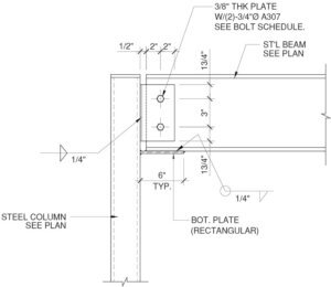
- Locate the bolts completely. Give bolt size, grade, quantity, gage, pitch, edge distances, and hole type. Check wrench access near the beam flanges and column web.
- Make the weld information specific. Distinguish web and flange welds, shop and field work, and any required preparation. Do not use a generic all-around symbol merely to avoid multiple callouts.
- Check surrounding steel. Review continuity plates, column stiffeners, adjacent framing, slab edges, deck, and fire protection for conflicts.
- Document approved fit-up provisions. Show shims, fillers, special holes, or other provisions only when they are part of the approved connection requirements.
- Keep the calculation and drawing aligned. A change in bolt rows, plate thickness, welds, support section, or geometry can invalidate a previous connection check.
Seismic use requires a specific qualified detail
For U.S. seismic work, a generic extended end plate should not be labeled “prequalified.” The connection must meet the applicable configuration, material, geometry, fabrication, and other limits of the governing provisions—or be qualified through the permitted alternative procedure. ANSI/AISC 358-22 Chapter 6 covers specified bolted unstiffened and stiffened extended end-plate moment connections; the project’s adopted standards and amendments still control. [5]
AISC Design Guide 39, End-Plate Moment Connections (2023), consolidates and updates the earlier guidance in Design Guides 4 and 16. AISC identifies those earlier guides as superseded. Use the applicable current project reference rather than carrying an old detail forward without review. [4]
End plate versus shear tab versus double angle
| Connection | Typical arrangement | Detailing focus |
|---|---|---|
| Shear end plate | Plate welded across beam end; bolted to support | Plate fit-up, bolt access, web welds, and rotation compatibility |
| Shear tab | Plate attached to support; beam web bolted to plate | Beam setback, web holes, plate projection, and support attachment |
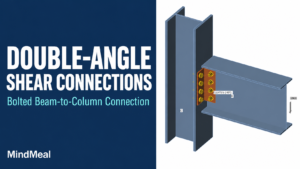
| Double-angle shear connection | Angles connect beam web to support | Angle orientation, both bolt lines or welds, access, and flexibility |
| Moment end plate | Plate attached to beam flanges and web; bolted to support | Tension/compression load path, prying, welds, column response, and frame requirements |
Frequently asked questions
Is every end-plate connection a moment connection?
No. Shear end plates and moment end plates are different connection applications. Determine the intended behavior from the design, not the name alone.
Is the end plate welded to the column?
In the common bolted end-plate arrangement discussed here, it is welded to the beam and bolted to the supporting column flange. Other configurations exist and need their own details.
Can the beam ever be welded directly to a column?
Yes. Directly welded beam-to-column connections are a different connection family. The absence of a direct beam-to-column weld in this end-plate detail is not a universal prohibition on welded moment connections.
Can I use the same detail for an HSS column?
Do not assume so. HSS walls introduce different access and local-strength questions. A detail developed for a wide-flange column flange does not automatically transfer to a closed HSS section.
How many bolts or what plate thickness should I use?
There is no universal value. The design forces, geometry, bolt and plate properties, weld requirements, supporting member, and intended behavior determine the detail. The illustrations on this page intentionally provide no fabrication sizes or capacities.
References and scope
[1] SCI / BCSA, Simple connections. Conceptual explanation of flexible end plates. UK/Eurocode numerical provisions are not adopted in this article.
[2] SCI / BCSA, Moment-resisting connections. Conceptual force transfer and connection components.
[3] AISC, Design of End-Plate Moment Connections Using Design Guide 39. AISC webinar description, December 2023; gravity/wind and seismic design scope.
[4] AISC, Design Guides for Download. Design Guide 39 supersedes Guides 4 and 16. See also ANSI/AISC 358-22 Chapter 6 for its specific seismic connection scope.
[5] ANSI/AISC 358-22, Chapter 6. Bolted unstiffened and stiffened extended end-plate moment connections; prequalification is subject to the standard’s limitations.
Reviewed October 20, 2026. This is an explanatory and drawing-review article, not a connection design calculation. Original diagrams are schematic and do not prescribe bolt layouts, weld sizes, plate thicknesses, or seismic qualification.
MindCore