Steel Beam Deflection: Limits, Calculations, and Design Considerations
A steel beam does not have to fail structurally to become a design problem.
In fact, a beam may have more than enough flexural strength to resist the applied loads and still be unsuitable for a building because it deflects too much.
Excessive deflection can lead to cracked finishes, uneven floors, damaged partitions, misaligned doors, drainage problems, and noticeable floor movement. For this reason, structural steel design is not simply a question of whether a beam is strong enough.
It must also be stiff enough.
This distinction separates two fundamental concepts in structural engineering: strength and serviceability.
This article examines steel beam deflection from an engineering perspective, including the mechanics behind deflection, common calculation methods, span-to-deflection limits, section properties, service-load considerations, and the practical decisions that can cause deflection—not strength—to control beam selection.
1. What Is Steel Beam Deflection?
Beam deflection is the displacement of a structural member from its original unloaded position when loads are applied.
Consider a simply supported steel beam spanning between two columns.
Before loading, the beam is approximately straight. Once floor dead load, occupancy load, mechanical equipment, partitions, or other loads are applied, bending moments develop within the member.
The beam responds by developing curvature.
The resulting vertical displacement is what engineers refer to as deflection, commonly represented by the Greek letter:
δ (delta)
For building beams, deflection is often measured in inches in U.S. customary units.
The important point is that deflection does not automatically indicate structural failure.
Elastic deflection is an expected part of structural behavior.
The design question is:
How much deflection is acceptable?
2. Strength Is Not the Same as Stiffness
This is one of the most important concepts in steel beam design.
A beam strength check evaluates whether the member has adequate resistance against applicable limit states such as flexural yielding, lateral-torsional buckling, shear, and other modes of failure.
A deflection check asks a different question:
Will the beam deform too much during normal use?
A beam can therefore satisfy its strength requirements while failing its serviceability requirements.
This occurs frequently with relatively long spans.
Increasing steel strength does not necessarily provide a proportional improvement in elastic deflection because ordinary elastic beam deflection depends primarily on:
- applied service load,
- span length,
- modulus of elasticity, and
- moment of inertia.
For structural steel, the modulus of elasticity normally used in design is approximately:
E = 29,000 ksi
Therefore, when two steel grades have the same cross-sectional geometry, changing yield strength alone does not significantly change their elastic stiffness.
This is why simply specifying higher-strength steel is not necessarily the solution to a deflection problem.
3. The Basic Steel Beam Deflection Equation
For a simply supported beam subjected to a uniformly distributed load across the entire span, the familiar elastic deflection equation is:
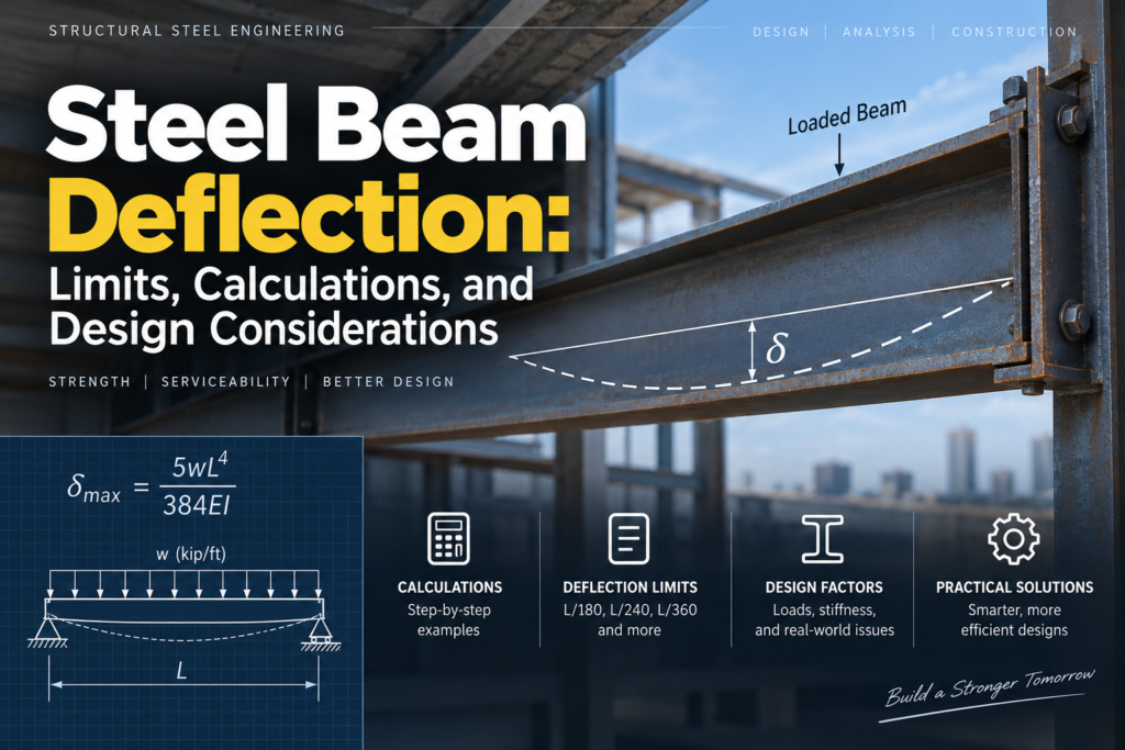
δmax = 5wL⁴ / (384EI)
where:
- δmax = maximum deflection
- w = uniformly distributed load
- L = beam span
- E = modulus of elasticity
- I = moment of inertia about the bending axis
For this loading condition, maximum vertical deflection occurs at midspan.
Although the equation appears straightforward, it reveals something extremely important about structural behavior.
Deflection is proportional to L⁴.
The span is raised to the fourth power.
That makes span length extraordinarily influential.
If all other variables remain unchanged and the span doubles:
2⁴ = 16
the theoretical deflection becomes sixteen times larger.
This is one reason why beam selection can change dramatically as structural bays become longer.
4. Why Moment of Inertia Matters
The term I in the deflection equation represents the section’s moment of inertia.
Moment of inertia is a geometric property describing how the cross-sectional area is distributed relative to the neutral axis.
For a W-shape bending about its strong axis, the relevant property is typically Ix.
A larger Ix means greater flexural stiffness and therefore less elastic deflection under the same loading conditions.
From:
δ ∝ 1 / EI
increasing either E or I decreases deflection.
Since the modulus of elasticity for conventional structural steels is essentially fixed for ordinary design purposes, engineers generally reduce beam deflection by increasing the member’s sectional stiffness EI, most practically by selecting a section with a larger moment of inertia.
This explains why beam depth is so influential.
Material located farther from the neutral axis contributes strongly to moment of inertia. Consequently, a deeper beam can often provide significantly greater stiffness without requiring a proportional increase in steel weight.
5. Deflection Limits: What Does L/360 Mean?
Structural drawings and calculations frequently contain criteria such as:
L/180
L/240
L/360
L/480
These expressions define allowable deflection as a fraction of the member span.
For example, consider a beam with a 30-foot span.
Convert the span to inches:
L = 30 × 12 = 360 in.
If the applicable deflection criterion is:
L/360
then:
δallowable = 360 / 360 = 1.00 in.
If the calculated deflection is:
0.72 in.
the beam satisfies that particular criterion.
If the calculated deflection is:
1.18 in.
it does not.
However, L/360 should never be treated as a universal steel-beam limit. The applicable criterion depends on the member, load being evaluated, supported construction, governing building code, project specifications, and other serviceability requirements.
6. Typical Building Deflection Criteria
Building-code deflection requirements vary according to the type of construction and the elements being supported.
Typical span-based limits encountered in building design include values such as L/180, L/240, and L/360.
For example, floor framing commonly encounters an L/360 live-load deflection criterion, while the permitted total-load deflection may be different.
Roof requirements can also vary substantially depending on whether the roof framing supports plaster or another ceiling system.
The important engineering principle is not to memorize one ratio and apply it everywhere.
Instead, determine:
- what structural member is being checked,
- what load component the limit applies to,
- what finishes or nonstructural elements are supported,
- what code edition governs the project, and
- whether the project specifications impose more restrictive requirements.
A beam supporting brittle architectural materials may require tighter control than a comparable beam supporting flexible components.
7. Service Loads vs. Factored Loads
Another common source of confusion is the load level used for deflection calculations.
Strength design using LRFD may involve factored load combinations.
Serviceability calculations are fundamentally concerned with the structure’s behavior under normal service conditions.
Therefore, engineers must distinguish between strength-level loading and service-level loading when evaluating deflection.
Using a strength load combination directly in a serviceability calculation can produce a misleading result.
This is one reason a professional beam calculation often contains separate sections for:
Strength Checks
and
Serviceability Checks
They answer different engineering questions.
8. Worked Example: Simply Supported Steel Beam
Consider a simplified floor beam:
Span: 24 ft
Uniform service load: 1.0 kip/ft
Modulus of elasticity: 29,000 ksi
Beam moment of inertia Ix: 600 in⁴
The span must first be converted to inches:
L = 24 × 12 = 288 in.
The distributed load must also use compatible units:
w = 1.0 kip/ft = 1/12 kip/in.
For a simply supported beam carrying uniform load:
δmax = 5wL⁴ / 384EI
Substituting the values:
δmax ≈ 0.43 in.
Now suppose the applicable criterion for the load being evaluated is L/360.
δallowable = 288 / 360
δallowable = 0.80 in.
Therefore:
Calculated deflection ≈ 0.43 in.
Allowable deflection = 0.80 in.
For this simplified example, the beam satisfies the assumed L/360 deflection criterion.
But this does not establish that the beam is adequately designed.
Flexural strength, shear, lateral stability, concentrated-force effects, connections, vibration, applicable load combinations, and other code requirements must still be evaluated.
That distinction is essential.
9. Why Long-Span Beams Often Become Deflection-Controlled
Return to the equation:
δ = 5wL⁴ / 384EI
Suppose the load and beam section remain unchanged, but the span increases from 20 ft to 30 ft.
The span increases by a factor of:
30 / 20 = 1.5
The corresponding theoretical change in deflection is:
1.5⁴ = 5.0625
In this simplified comparison, the beam could experience more than five times the deflection.
This illustrates why a section that performs comfortably over a shorter span can become completely unsuitable after what appears to be a modest increase in span.
It also explains an important phenomenon in structural design:
The lightest beam that passes strength may not be the beam that satisfies the project.
Serviceability can force the designer to select a deeper or heavier member.
10. Live-Load Deflection vs. Total-Load Deflection
Not all deflection checks measure the same thing.
Engineers may need to evaluate several responses separately.
Live-load deflection
This represents deformation associated primarily with occupancy or other applicable variable loads.
It is often important for floors because excessive movement can affect finishes and occupant perception.
Dead-load deflection
Dead load includes permanent structural and nonstructural weight.
Examples include:
- steel self-weight,
- floor slab,
- permanent ceilings,
- fixed architectural components.
Total-load deflection
This considers the applicable combined service loads.
A structural drawing might therefore specify different limits for live-load deflection and total deflection.
Reading only the denominator—such as “360”—without identifying the associated load case is incomplete.
11. Deflection and Camber Are Not the Same Thing
Camber is an intentional upward curvature introduced into a beam, often to compensate for anticipated downward deflection.
Suppose a long-span beam is expected to deflect downward under permanent load.
A specified upward camber can reduce the visible sag after those loads are applied.
But camber does not increase the beam’s fundamental elastic stiffness.
It does not change E.
It does not inherently increase I.
And it does not eliminate incremental deflection produced by future live load.
Therefore:
Camber is not a substitute for adequate beam stiffness.
It is a tool for controlling geometry and anticipated floor elevation under specified loading conditions.
12. Composite Beams Require Additional Consideration
Many steel floor systems use steel beams connected to a concrete slab through shear connectors.
Once composite action is developed, the slab and steel beam can act together structurally.
This changes the effective stiffness of the system.
However, construction sequence becomes important.
Before the concrete develops adequate strength, the steel beam may have to support:
- its own weight,
- metal deck,
- wet concrete,
- construction loading.
At that stage, the steel section may be acting alone.
After composite action develops, the structural system has different stiffness characteristics.
Consequently, composite-beam deflection may need to distinguish between pre-composite and post-composite behavior.
This is considerably more involved than simply inserting a composite moment of inertia into one equation.
13. Deflection Can Affect More Than the Beam
Excessive beam movement can influence components that are not part of the beam’s strength calculation.
Potential consequences include:
- cracking of gypsum or plaster finishes,
- distress in brittle partitions,
- floor elevation differences,
- ceiling alignment problems,
- curtain-wall or cladding interaction,
- drainage and roof slope issues,
- misalignment of supported equipment,
- noticeable floor movement.
This illustrates why serviceability is a system-level concern.
A steel beam might remain completely elastic while the elements attached to it experience unacceptable performance.
14. Practical Ways to Reduce Steel Beam Deflection
When deflection controls a beam design, several strategies may be considered.
Increase beam depth.
A deeper section can significantly increase moment of inertia and is often one of the most efficient methods of improving stiffness.
Select a section with larger Ix.
Two W-shapes with similar weights can have substantially different stiffness depending on how their material is distributed.
Reduce the span.
Because deflection is strongly dependent on span, adding an intermediate support can dramatically change structural behavior.
Use composite action where appropriate.
Composite floor construction can increase effective stiffness after composite action develops.
Modify framing layout.
Reducing tributary width or changing beam spacing can decrease load carried by individual members.
Control loading.
Heavy partitions, mechanical units, storage areas, façade reactions, and other concentrated or distributed loads can significantly affect deflection.
Consider camber where appropriate.
Camber can compensate for anticipated permanent-load deflection, although it should not be confused with increased stiffness.
The appropriate solution depends on architecture, structural behavior, fabrication, cost, depth restrictions, MEP coordination, and construction sequence.
15. A Beam Can Pass Strength and Still Be a Poor Design
Imagine two candidate W-shapes.
Both have sufficient flexural and shear capacity.
Beam A is relatively shallow and has a smaller Ix.
Beam B is deeper and has a significantly larger Ix.
From a pure strength perspective, Beam A may appear more economical.
But if Beam A produces excessive floor movement while Beam B satisfies the required serviceability criteria, the lighter beam is not necessarily the better design.
This demonstrates an important principle:
Structural efficiency is not simply minimum steel weight.
A successful structural member must satisfy strength, stability, serviceability, constructability, coordination, and project-specific performance requirements.
16. Common Mistakes When Evaluating Beam Deflection
Several mistakes repeatedly appear in simplified beam evaluations.
Applying L/360 automatically.
L/360 is common, but it is not a universal deflection limit.
Using factored strength loads for every deflection calculation.
Strength and serviceability load levels should not be confused.
Assuming higher Fy means a much stiffer beam.
Elastic stiffness is governed by EI, not yield strength alone.
Ignoring construction-stage deflection.
This can be particularly important for composite floor systems.
Using the wrong moment of inertia.
Strong-axis and weak-axis properties can differ enormously.
Assuming camber solves a stiffness problem.
Camber changes initial geometry; it does not fundamentally increase EI.
Checking only the steel member.
Supported partitions, ceilings, façades, equipment, roofing, and other systems may impose stricter performance requirements.
17. What Structural Drawings Should Communicate
Deflection is not only a calculation issue.
It can become a drawing and coordination issue as well.
Depending on the project, structural documents may need to communicate information such as:
- specified beam camber,
- floor elevation requirements,
- framing orientation,
- beam size and location,
- special loading conditions,
- connection assumptions,
- composite construction requirements,
- deflection criteria where necessary,
- coordination requirements for sensitive supported elements.
A calculation that never makes its design assumptions clear to the drawing team, fabricator, or contractor can create problems later in the project.
This is where structural analysis and structural drafting intersect.
18. Final Perspective
Steel beam design is sometimes simplified into a strength problem:
How much load can this beam carry?
Professional structural design requires another question:
How will this beam behave while carrying the loads it encounters during normal use?
Deflection is one of the clearest examples of why these questions are different.
A beam can possess adequate strength and still exhibit unacceptable serviceability performance. Span, loading, moment of inertia, boundary conditions, composite behavior, supported finishes, and construction sequence can all influence the result.
Understanding this distinction is essential when selecting steel members, reviewing structural calculations, preparing drawings, or coordinating steel framing with architectural and building systems.
The goal is not merely to prevent failure.
The goal is to create a structure that performs as intended.
Technical Reference Note
For U.S. projects, applicable requirements should be verified using the governing edition of the building code and referenced structural standards. ANSI/AISC 360 addresses structural steel design, while AISC Design Guide 3 provides additional discussion of serviceability considerations for steel buildings.
Actual design criteria can vary by jurisdiction, occupancy, structural system, supported construction, project specifications, and adopted code edition.
This article is intended for technical education and should not be used as a substitute for project-specific engineering calculations or the judgment of the responsible licensed structural engineer.
MindCore