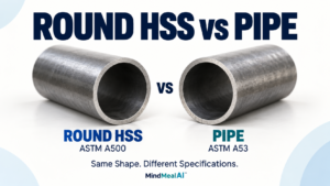
Steel Connection Design: How Forces Travel Through Bolts, Welds, and Plates
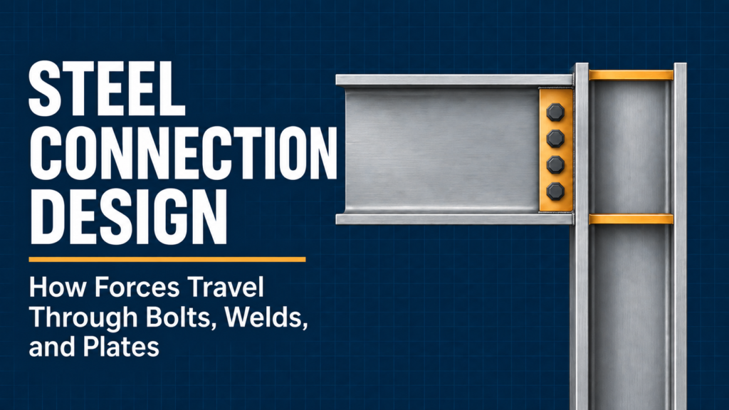
A beam-end detail may show four bolts, a plate, and two weld lines. Those components must transfer the beam reaction into the supporting structure while accommodating the movement assumed in the structural analysis.
Steel connection design requires an understanding of both force transfer and deformation. For engineers and drafters reviewing drawings, that understanding explains why a small change in plate projection, hole location, or beam setback may require engineering review.
This article follows a typical single-plate shear connection, connects potential failure modes to drawing dimensions, and demonstrates why dividing a reaction by the number of bolts can be misleading.
The discussion uses U.S. structural steel terminology. The numerical example illustrates force distribution under stated assumptions; it is not a complete connection design or a construction detail.
1. Define What the Connection Must Transfer
Before selecting bolts, plates, or welds, identify the required forces and the intended behavior of the joint.
For a beam-end connection, the necessary information may include:
- Vertical shear.
- Axial tension or compression.
- Moment, where required.
- Load reversal or uplift.
- Required rotation and restraint.
- Whether the specified forces are LRFD or ASD demands.
A reaction labeled “24 kips” needs a clear design basis. A factored LRFD demand is compared with LRFD design strength, while an ASD demand is compared with allowable strength.
A simple connection accommodates beam-end rotation while transferring its specified forces. However, a beam end modeled as pinned can still have local moments within its connection.
A pinned assumption in the frame model does not mean every bolt, plate, and weld experiences only direct shear.
Offsets and component stiffness influence how forces are distributed within the joint.
2. Follow the Load Through a Single-Plate Shear Connection
Consider a W-shape beam whose web is bolted to a vertical steel plate. The plate is welded to a supporting column flange.
For a bearing-type force-transfer model, the load passes through several components and interfaces.
| Component or interface | Role in the load path |
|---|---|
| Beam web | Carries the beam-end reaction into the connection region |
| Beam-web holes | Transfer force through contact with the bolts |
| Bolts | Carry shear across the interface between the web and plate |
| Plate holes | Receive force from the bolts through bearing |
| Plate body | Transfers force from the bolt group toward the weld |
| Weld group | Transfers force into the supporting column |
| Supporting column | Receives and distributes the connection forces |
This sequence explains why bolt strength alone cannot establish connection adequacy.
For example, changing a beam to a lighter W-shape may leave the bolt arrangement unchanged while reducing the beam-web thickness. The detail may still fit, but the material around the beam-web holes needs to be checked again.
Similarly, increasing the connection plate thickness does not strengthen the beam web on the opposite side of the bolts.
Each component must carry the forces assigned to it by a consistent connection model.
3. Match Potential Failure Modes to Drawing Dimensions
A limit state describes a condition beyond which a component no longer meets the required performance.
The following table connects common connection limit states with information that should be visible in drawings or specifications. The applicable checks depend on the actual detail and loading.
| Potential limit state | What can happen | Information to examine |
|---|---|---|
| Bolt shear | A bolt fails across a shear plane | Bolt grade, diameter, number, and connected-ply arrangement |
| Bearing at holes | Material deforms locally against a bolt | Plate thickness, beam-web thickness, hole size, material strength |
| Tearout | Material fails between a hole and an edge or adjacent hole | Clear distance in the force direction, spacing, edge distance |
| Block shear | A block separates along combined shear and tension paths | Bolt layout, free edges, plate outline, beam-end geometry |
| Plate shear yielding or rupture | A gross or net section cannot carry the shear | Plate depth, thickness, holes, and relevant failure section |
| Plate bending or instability | The plate cannot sustain bending or remain stable | Projection, thickness, restraint, and connection configuration |
| Weld or adjacent base-metal failure | Force transfer fails at or beside the weld | Weld size, effective length, connected thickness, material properties |
| Local failure of the support | The supporting flange, web, or wall cannot receive the load | Supporting member section, attachment location, reinforcement |
A connection should be reviewed as an assembly. Strengthening one part may leave another part as the controlling component.
Edge Distance and Clear Distance Are Different
An edge distance commonly locates the center of a hole relative to the material edge. Clear distance measures the material remaining between the hole boundary and the relevant edge or neighboring hole.
For a round hole:
Clear distance to an edge = center-to-edge distance − half the hole diameter
Suppose the center-to-edge dimension is 1.50 inches and the hole diameter is 13/16 inch.
Clear distance = 1.50 − 0.8125/2 = 1.094 inches
This calculation identifies the remaining material. It does not establish whether the connection satisfies the applicable requirements.
If the hole becomes larger while its center stays in the same location, the center-to-edge dimension remains unchanged, but the clear distance decreases.
That is why a hole-size revision can affect connection strength even when the bolt centers do not move.
4. Why Dividing the Reaction by the Bolt Count Can Be Misleading
Dividing the reaction by the number of bolts gives the direct-shear component for an idealized group of identical bolts. An eccentric force can introduce additional demand.
Consider the following separate, idealized bolt-group example.
| Assumption | Value |
|---|---|
| Applied vertical force, V | 24 kips |
| Number of identical bolts | 4 |
| Bolt layout | One vertical line |
| Vertical bolt spacing | 3 inches |
| Horizontal force offset from group centroid, e | 3 inches |
| Analysis model | Rigid plate with equal bolt shear stiffness |
| Loading | In-plane shear and moment only |
The eccentricity in this example is measured from the bolt-group centroid to the applied force line. It should not automatically be substituted for the effective design eccentricity of an actual beam shear connection.
Step 1: Calculate Direct Shear
The direct vertical shear per bolt is:
V / n = 24 / 4 = 6.0 kips
If the force passed through the group centroid, this would be the only component in the stated model.
Step 2: Calculate the Moment
The horizontal offset produces:
M = V × e = 24 × 3 = 72 kip-in.
With four bolts spaced 3 inches apart, their vertical distances from the group centroid are:
−4.5, −1.5, +1.5, and +4.5 inches
The sum of the squared distances is:
Σr² = 4.5² + 1.5² + 1.5² + 4.5² = 45 in²
Step 3: Calculate the Moment-Induced Bolt Forces
For the stated elastic model:
Fₘ = M × r / Σr²
Here, r is the distance from the bolt-group centroid to the bolt being evaluated.
Because all four bolts lie on a vertical line, their moment-induced forces are horizontal. The forces above and below the centroid act in opposite directions.
For either outer bolt:
Fₘ = 72 × 4.5 / 45 = 7.2 kips
For either inner bolt:
Fₘ = 72 × 1.5 / 45 = 2.4 kips
Step 4: Combine the Components
The direct vertical shear and moment-induced horizontal shear are perpendicular, so their resultant is:
Resultant shear = √(vertical shear² + horizontal shear²)
| Bolt position | Direct vertical shear | Horizontal shear magnitude | Resultant shear |
|---|---|---|---|
| Outer bolts | 6.0 kips | 7.2 kips | 9.37 kips |
| Inner bolts | 6.0 kips | 2.4 kips | 6.46 kips |
The maximum demand is approximately 56% higher than the 6.0-kip value obtained by simply dividing the reaction by four.
This calculation establishes bolt forces under the stated assumptions. It does not establish bolt capacity, hole bearing strength, plate strength, or weld adequacy.
For an actual single-plate beam connection, the analysis procedure must account for its geometry, restraint, and deformation behavior. A conventional shear-tab design procedure should not be replaced casually with a generic rigid-bracket model.
5. Distinguish Bolt Strength From Slip Resistance
Bolt strength and slip resistance address different aspects of connection performance.
In a bearing-type joint, shear transfer is evaluated through bolt shear and bearing of the connected material.
A slip-critical joint is designed to resist slip at the contacting surfaces, called faying surfaces, through friction developed by bolt pretension.
A pretensioned joint is not automatically slip-critical. Slip-critical performance also depends on the specified surface condition and other joint requirements.
Drawings and specifications should identify the required bolt assembly, hole configuration, installation condition, and any slip-critical requirements. A note stating only “high-strength bolts” may not communicate enough information.
For bolt strength, the grade, diameter, number of shear planes, and presence of threads in the shear plane also matter.
6. Read the Weld as a Complete Interface
A weld callout must identify more than a nominal size.
For a conventional equal-leg fillet weld joining surfaces at 90 degrees, the theoretical throat is approximately:
Theoretical throat = 0.707 × weld leg size
A 1/4-inch leg therefore gives:
0.707 × 0.25 = 0.177 inch
This geometric relationship explains why the weld leg and throat are different dimensions. The effective throat used in design must match the actual joint geometry and applicable welding provisions.
When reviewing a weld detail, identify:
- Which side or sides of the plate are welded.
- The effective weld length.
- Where each weld starts and stops.
- Whether the weld is made in the shop or field.
- Whether the joint is accessible for welding and inspection.
For a simple, uniformly loaded weld model, dividing force by effective weld length provides an average force per unit length. An eccentric weld group requires evaluation of the additional effects of moment.
Increasing weld size does not establish that the adjacent plate or supporting member is adequate. The entire force-transfer interface needs to be considered.
7. Recognize Revisions That Can Change Connection Behavior
Drawing coordination often involves small adjustments. Some affect structural behavior as well as fit-up.
Increasing the Beam Setback
Moving the beam end away from the support may require a longer plate projection.
Determine whether the bolt line also moves. Changing the beam end alone is not necessarily equivalent to moving the complete bolt group.
A useful review compares the locations of the support face, weld line, bolt line, and beam end before and after the revision.
Enlarging a Beam Cope
A cope can resolve interference between intersecting steel members while reducing the remaining beam-end section.
Cope length and depth should therefore be coordinated with the engineering design. A clearance solution should not be treated as purely cosmetic.
Substituting a Thicker Plate
A thicker plate can change stiffness as well as strength.
A simple connection still needs to accommodate the required rotation. Conventional and extended single-plate connections have different design considerations, and a revised detail must remain within the assumptions of its selected design procedure.
Moving a Bolt Hole
A hole moved to improve access may alter edge distance, spacing, eccentricity, or the potential failure path through the material.
The change should be reviewed against the connection geometry as a whole.
A precise coordination note helps the engineer evaluate the revision:
“The beam setback has increased by 1 inch, and the bolt line has moved with the beam. Please confirm the revised plate projection, connection forces, and weld requirements.”
8. Use a Focused Drawing Review Checklist
Before releasing a connection detail, compare the framing plan, schedules, sections, and calculations.
| Review item | Question to resolve |
|---|---|
| Design forces | Are required forces and the LRFD/ASD basis identified? |
| Member sizes | Does the detail use the actual beam and supporting member? |
| Plate geometry | Are thickness, depth, projection, and material specified consistently? |
| Bolt layout | Do count, spacing, hole type, and edge dimensions agree in every view? |
| Beam end | Are setback and cope dimensions coordinated? |
| Welds | Are size, location, extent, and shop/field designation clear? |
| Access | Can bolts be installed and tightened, and can welds be made and inspected? |
| Revisions | Have changes affecting the load path received the required engineering review? |
A practical connection review begins by tracing the force, then identifying the material and fasteners that carry it.
When a dimension changes, return to that path and ask which component’s demand, strength, or deformation has changed. This approach helps engineers and drafters produce details that communicate both design intent and construction requirements.
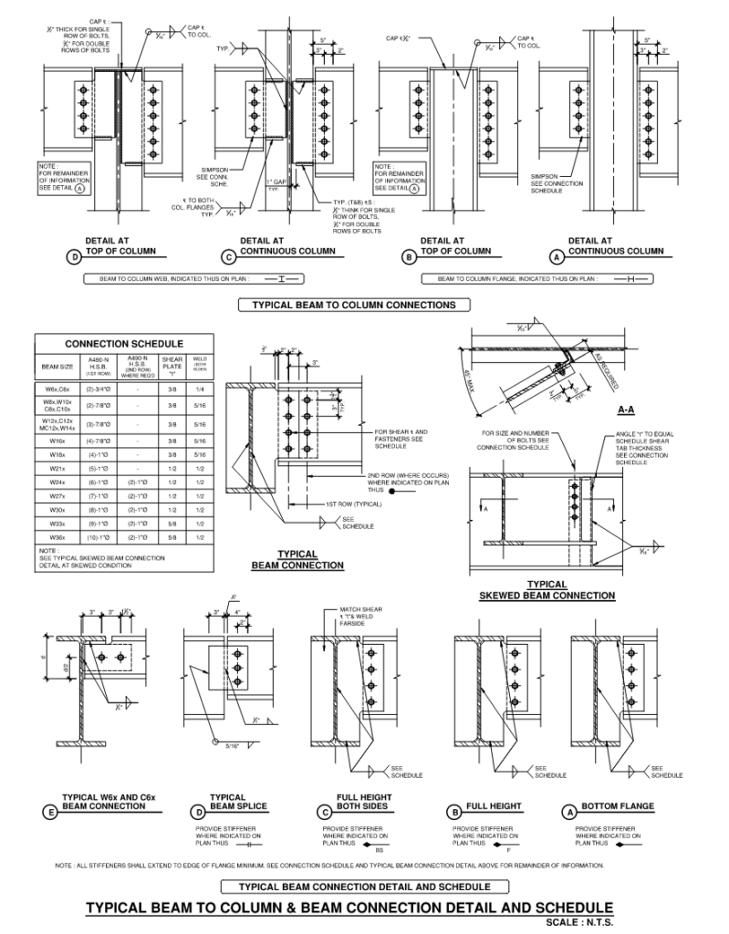
Example connection details illustrating bolt layouts, shear plates, welds, and drawing coordination. These details are separate from the simplified bolt-group calculation above; connection sizes require project-specific engineering verification.
References
These references support the discussion of bolted joints and single-plate connection behavior. The older research papers provide background on design-method development; project design should use the applicable adopted standards and current design guidance.
- Research Council on Structural Connections. Specification for Structural Joints Using High-Strength Bolts. June 11, 2020. Read specification.
- Muir, L. S., and Thornton, W. A. “The Development of a New Design Procedure for Conventional Single-Plate Shear Connections.” Engineering Journal, 48(2), 141–152, 2011. View publication.
- Muir, L. S., and Hewitt, C. M. “Design of Unstiffened Extended Single-Plate Shear Connections.” Engineering Journal, 46(2), 67–80, 2009. View publication.
MindCore