W-Shape Selection: How Engineers Choose Steel Beams
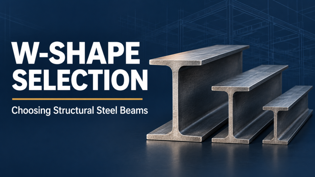
Choosing a W-shape starts with the loads a beam must carry, but it does not end there. The beam must also limit deflection, remain stable, fit its connections, and provide enough clearance within the building.
A suitable beam needs adequate strength, adequate stiffness, and practical detailing. Understanding these three requirements makes a steel table much easier to use.
1. Read the W-Shape Designation Correctly
A designation such as W18×35 identifies a wide-flange steel section with a nominal depth of approximately 18 inches and a nominal weight of 35 pounds per foot.
The designation does not tell you the exact depth or how much load the beam can support.
When comparing sections, start with these properties:
| Property | What It Helps You Check |
|---|---|
| Actual depth, d | Clearance below the beam |
| Flange width, bf | Fit at supports and connections |
| Web and flange thickness, tw and tf | Local behavior and connection requirements |
| Moment of inertia, Ix | Resistance to bending deflection |
| Plastic section modulus, Zx | Preliminary bending strength under applicable conditions |
| Weight per foot | Beam self-weight and material quantity |
A W-shape dimensions table helps identify candidates. It is not a load-capacity table.
2. Establish the Loads, Span, and Supports
Before selecting a section, determine the beam’s actual job.
Important information includes its span, support conditions, supported floor or roof area, distributed loads, and any concentrated loads from other members or equipment. Beam self-weight must also be included.
The available depth and lateral bracing locations matter as well.
Span length and unbraced length are different. Span describes the distance between supports in the structural model. Unbraced length relates to the spacing of effective restraints against lateral movement or twisting.
A beam can have adequate vertical support at both ends and still need intermediate lateral restraint.
3. Check Strength, Deflection, and Stability
These checks answer different questions.
Strength: Can the beam resist the forces?
Engineers calculate bending moments and shear forces using the applicable design loads, then compare them with the section’s available strength.
For a compact W-shape with adequate lateral bracing, the plastic section modulus, Zx, can help screen candidates for bending strength. However, that screening alone does not complete the design.
Deflection: Will the beam bend too much?
A beam can pass its strength checks and still deflect enough to affect finishes, partitions, or equipment.
Elastic bending deflection depends on load, span, support conditions, and stiffness. For a given steel grade and loading arrangement, a larger Ix generally means less bending deflection.
Using higher-strength steel alone does not meaningfully improve elastic stiffness.
Stability: Can the beam move sideways and twist?
An inadequately restrained W-shape may experience lateral-torsional buckling before reaching its full yielding-based bending strength.
Engineers therefore check the actual bracing arrangement. They also consider construction stages, when the completed floor system may not yet provide restraint.
4. A Simple Example of Narrowing the Options
Consider a hypothetical simply supported, noncomposite floor beam carrying a uniform load:
| Assumption | Value |
|---|---|
| Span | 25 ft |
| Dead load, including estimated beam weight | 0.60 kip/ft |
| Live load | 0.80 kip/ft |
| Steel yield stress | 50 ksi |
| Elastic modulus | 29,000 ksi |
| Assumed live-load deflection limit | L/360 |
| Assumed total-load deflection limit | L/240 |
These deflection limits are illustrative assumptions. Actual criteria depend on the project and supported construction.
Using the LRFD load combination 1.2D + 1.6L, the factored uniform load is 2.00 kip/ft, producing a maximum bending moment of 156.25 kip-ft.
For a preliminary bending screen, assume a compact section with sufficient lateral restraint to develop its plastic moment and a flexural resistance factor of 0.90.
The screening results are:
| Preliminary Check | Required Property |
|---|---|
| Yielding-based bending strength | Zx ≥ 41.7 in³ |
| Live-load bending deflection | Ix ≥ 291 in⁴ |
| Total-load bending deflection | Ix ≥ approximately 340 in⁴ |
The useful lesson is that bending strength and stiffness must both be checked.
A candidate with enough Zx but an Ix of only 320 in⁴ would fail the assumed total-load deflection requirement. A candidate meeting both property thresholds would remain a possibility, subject to the other design checks.
These results do not establish a final beam size.
5. Confirm That the Beam Fits the Connections and Drawings
Once a candidate passes the initial checks, review how loads enter and leave the member.
Support reactions and concentrated loads may require checks of the web, stiffeners, and connection components. The proposed bolts, plates, and copes must also fit within the actual section geometry.
For drafting and coordination, nominal depth is especially easy to misread. Sections in the same W-depth series can have different actual depths.
If the top-of-steel elevation stays fixed and the replacement section is deeper, the bottom flange moves downward. That can reduce clearance for ducts, ceilings, or door heads.
Before changing a beam size, confirm:
- Actual depth and flange width
- Top-of-steel and bottom-of-steel elevations
- Space for connection plates and bolts
- Clearance at the web-to-flange fillet
- Matching updates in plans, sections, and schedules
A beam revision can affect several drawings, even when only one member size changes.
6. Compare the Installed Cost
The lightest acceptable section is not always the least expensive to install.
A slightly heavier beam may simplify a connection, eliminate stiffeners, or be more readily available. Repeating a smaller number of section sizes may also simplify fabrication and erection.
The final choice should consider material weight, connections, fabrication, availability, and coordination together.
Key Takeaways
- Start with the loads and structural arrangement. A beam designation alone cannot establish capacity.
- Check strength and stiffness separately. A strong beam can still deflect too much.
- Verify lateral restraint. Bracing affects available bending strength.
- Use actual dimensions. Nominal depth is not enough for detailing or clearance checks.
- Review the complete installation. Connections and fabrication can influence the preferred section.
The example illustrates preliminary selection only. Final design requires the applicable strength, serviceability, stability, and connection checks for the project.
MindCore