Lateral-Torsional Buckling of Steel Beams: What Controls Beam Capacity?
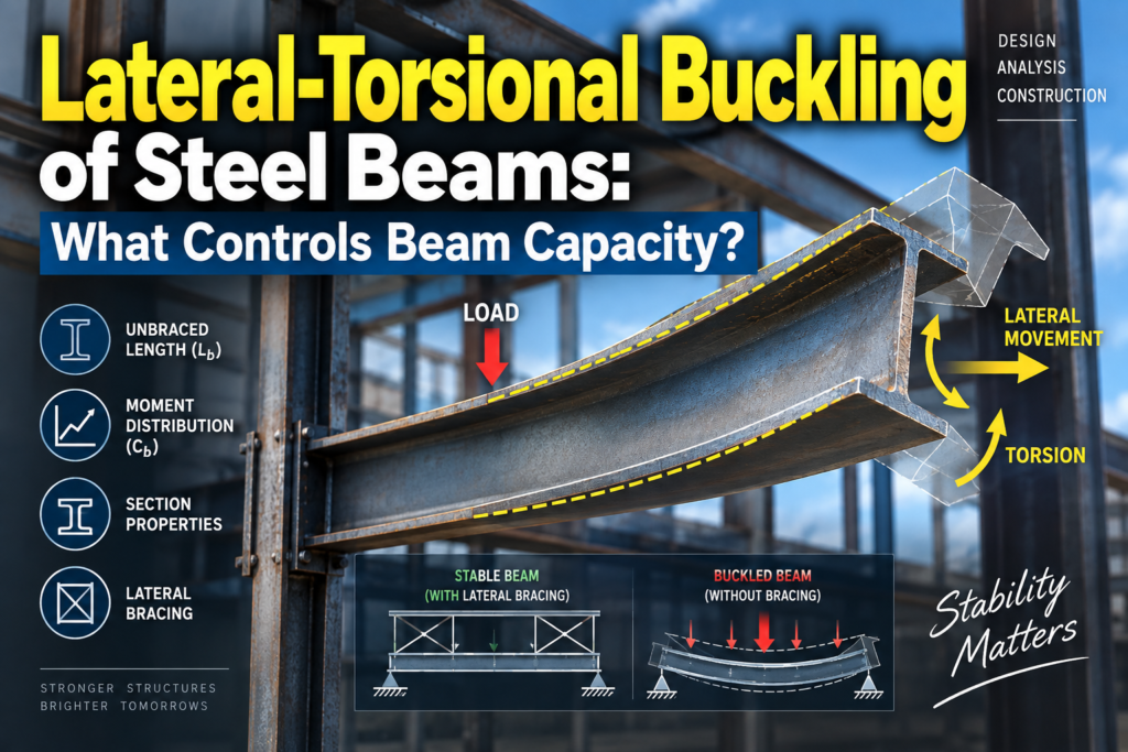
A steel beam may have enough material to resist the required bending moment and still fail to develop its full flexural strength.
Why?
Because beam capacity is not controlled by material strength alone.
For a wide-flange steel beam bending about its major axis, the compression flange can become laterally unstable. Once that flange begins moving sideways, the entire cross section can rotate and twist.
This behavior is known as lateral-torsional buckling (LTB).
LTB is one of the most important stability limit states in structural steel design because it explains why two identical W-shapes carrying similar bending moments can have very different available strengths simply because their unbraced lengths are different.
To understand beam capacity, therefore, we need to look beyond Fy and section modulus.
We need to understand stability.
1. What Is Lateral-Torsional Buckling?
Consider a simply supported W-shape subjected to downward gravity loading.
The beam bends about its strong axis.
Under positive bending:
- the top flange is primarily in compression,
- the bottom flange is primarily in tension.
If the compression flange is adequately restrained against lateral movement, the beam can develop substantial flexural strength.
But suppose the compression flange is unrestrained over a long distance.
As bending moment increases, the compression flange may attempt to move sideways.
Because the flange is connected to the web and opposite flange, this lateral movement does not occur independently. The entire cross section begins to rotate.
The beam therefore experiences two movements simultaneously:
Lateral displacement + twisting
That coupled instability is lateral-torsional buckling.
The beam is no longer bending purely in its intended vertical plane.
2. Why Does the Compression Flange Want to Move Sideways?
A useful way to visualize the behavior is to compare the compression flange of a beam with a compression member.
A long, slender compression member is susceptible to buckling.
The compression flange of a bending member has a similar stability problem, although the behavior of the entire beam is considerably more complex.
The compression flange wants to move laterally.
The tension flange, web, torsional stiffness, and warping resistance of the cross section resist that movement.
As the unbraced length increases, however, the beam becomes increasingly vulnerable to instability.
This leads to one of the most important variables in LTB design:
Lb = laterally unbraced length
Lb is generally the distance between points that provide appropriate lateral restraint to the compression flange and the necessary restraint against twist.
A longer Lb generally means lower lateral-torsional buckling strength.
3. Beam Strength Is Not Controlled by Fy Alone
Suppose two beams use the same W-shape and steel grade.
They have identical:
- yield strength Fy,
- flange dimensions,
- web dimensions,
- section modulus,
- moment of inertia,
- torsional properties.
Beam A is continuously or closely braced.
Beam B has a long unbraced segment.
Their material strength is identical.
Their cross sections are identical.
Yet their flexural capacities may not be identical.
Beam B may experience lateral-torsional buckling before it can develop the same bending resistance as Beam A.
This demonstrates a fundamental principle:
Section capacity and member capacity are not always the same thing.
The cross section may theoretically be capable of developing a large bending moment, but the member must remain stable long enough to develop that resistance.
4. The Three Important Lengths: Lb, Lp, and Lr
For common compact, doubly symmetric I-shaped members bent about their major axis, the AISC beam-strength framework uses three important lengths:
Lb — actual unbraced length
Lp — limiting laterally unbraced length for the plastic behavior region
Lr — limiting unbraced length separating inelastic and elastic LTB behavior
Comparing Lb with Lp and Lr helps determine which flexural behavior governs.
Conceptually, the beam-strength curve can be divided into three regions.
Region 1: Lb ≤ Lp
When the beam is sufficiently braced, lateral-torsional buckling does not reduce the nominal flexural strength below the plastic moment for the applicable compact-section case.
The member can potentially develop:
Mn = Mp
where:
Mp = Fy Zx
and:
- Fy = specified minimum yield stress
- Zx = plastic section modulus about the major axis.
This is the region where the beam can make the fullest use of its plastic flexural capacity, subject to the other applicable limit states and assumptions.
5. Region 2: Lp < Lb ≤ Lr
Now increase the distance between brace points.
The beam enters the inelastic lateral-torsional buckling region.
It is no longer sufficiently braced to automatically develop Mp throughout this range.
However, it has not yet entered the fully elastic LTB region.
The nominal flexural strength decreases as Lb increases.
This middle region is important because beam capacity is transitioning from plastic behavior toward stability-controlled behavior.
In simplified conceptual terms:
Increasing Lb → decreasing Mn
The actual AISC equations account for the applicable section and moment-gradient behavior rather than treating this as a simple universal linear rule for every beam configuration.
6. Region 3: Lb > Lr
When the unbraced length exceeds Lr, the beam enters the elastic lateral-torsional buckling region for the common case being discussed.
Now stability has become the dominant issue.
The beam can buckle laterally and twist while much of the section remains elastic.
In this region, increasing steel yield strength alone may provide much less benefit than someone unfamiliar with stability might expect.
Why?
Because the beam’s ability to resist LTB depends heavily on its geometry, torsional behavior, warping resistance, unbraced length, and moment distribution.
This is a critical distinction between:
Material failure
and
Stability failure.
7. What Actually Controls Lateral-Torsional Buckling?
Several variables strongly influence LTB capacity.
Unbraced Length — Lb
This is usually one of the first variables engineers examine.
Shorter unbraced lengths generally improve flexural strength because the compression flange has less distance over which to become laterally unstable.
Longer unbraced lengths generally increase susceptibility to LTB.
But Lb is not the only variable.
8. Section Geometry Matters
Two beams with similar weight can behave differently in lateral-torsional buckling.
Important section properties include:
- weak-axis moment of inertia,
- torsional constant,
- warping constant,
- flange geometry,
- web geometry,
- radius of gyration,
- section symmetry.
For wide-flange shapes, the flanges provide much of the resistance to major-axis bending, while the entire cross section participates in lateral and torsional stability.
This is why simply comparing beam weight or strong-axis section modulus does not provide a complete picture of LTB resistance.
A member is a three-dimensional object.
Its stability must also be understood three-dimensionally.
9. What Is Cb?
Real beams rarely experience a perfectly uniform bending moment over an entire unbraced segment.
The moment may be high near one location and significantly lower elsewhere.
AISC accounts for this using the lateral-torsional buckling modification factor Cb for applicable cases.
Cb represents the effect of the moment gradient within an unbraced segment.
For certain common conditions, a nonuniform moment distribution can provide greater LTB resistance than uniform moment at the same maximum moment.
Conceptually:
Uniform high moment over the entire unbraced segment
can be more critical than:
A localized maximum moment with substantially lower moments elsewhere.
This is why Cb can have a meaningful effect on calculated flexural strength.
It should not, however, be treated as an arbitrary multiplier.
Its use depends on the actual moment diagram, boundary conditions, brace locations, member symmetry, loading, and applicable AISC provisions.
10. Why Moment Gradient Changes LTB Capacity
Imagine two identical beams with the same Lb and the same maximum bending moment.
Beam A
The bending moment remains close to its maximum value throughout most of the unbraced segment.
Beam B
The maximum moment occurs near one location and decreases substantially toward the brace points.
Although both beams have the same Mmax, their stability conditions are not identical.
Beam A has a larger portion of the unbraced segment subjected to severe compression-flange stress.
Beam B has a more favorable moment gradient.
Therefore, the second beam may possess greater lateral-torsional buckling resistance.
This is precisely why engineers cannot determine LTB capacity using maximum moment alone.
The shape of the moment diagram matters.
11. What Counts as Lateral Bracing?
This is where structural design becomes especially interesting.
A beam touching another structural component does not automatically mean that it is adequately braced for LTB.
Effective bracing must provide sufficient restraint to control the relevant lateral movement and/or twisting behavior.
Depending on the structural system, restraint may come from components such as:
- floor framing,
- properly attached metal deck,
- diaphragms,
- cross frames,
- bridging systems,
- perpendicular beams,
- specifically designed brace members.
But engineers must verify whether the assumed restraint actually exists and whether it has adequate stiffness and strength.
This creates an important connection between structural calculations and construction documents.
If the analysis assumes a brace point but the physical structure does not provide the required restraint at that location, the calculated beam capacity may not represent the actual member behavior.
12. The Compression Flange Can Change
For a simple gravity beam under positive bending, the top flange is typically the compression flange.
But structural systems are not always that simple.
Moment reversal can occur.
For example, continuous framing can develop negative moment near supports.
In that region:
the bottom flange may become the compression flange.
This means that a restraint system effective for the top flange does not automatically provide the required restraint to the bottom flange.
Engineers therefore need to understand the actual moment diagram rather than assuming:
Top flange = compression flange everywhere.
That assumption can be incorrect.
13. Cantilevers Require Special Attention
Cantilever beams deserve particular care when evaluating LTB.
Their loading, support conditions, warping restraint, and compression-flange behavior differ from those of simply supported beams.
AISC provisions recognize that cantilever conditions require appropriate treatment of Cb and boundary conditions.
The intuitive rules used for a simply supported gravity beam should not automatically be transferred to a cantilever.
The correct analysis depends on:
- loading direction,
- unbraced length,
- restraint at the fixed end,
- warping behavior,
- load application,
- cross-sectional properties.
This is another example of why LTB is fundamentally a stability problem rather than merely a bending-stress calculation.
14. Load Position Can Affect Stability
Where the transverse load is applied relative to the cross section can also influence actual LTB behavior.
A load applied above the shear center can have a destabilizing effect in some configurations.
A load applied in a more favorable position may have a stabilizing influence.
This is especially relevant when examining unusual framing, crane beams, suspended loads, or members where loading does not act in the conventional manner assumed in simplified beam models.
The key lesson is:
A beam is not merely a line on a structural analysis model.
Real loads enter a real three-dimensional cross section at physical locations.
15. Lateral-Torsional Buckling vs. Local Buckling
These two limit states are often confused.
They are not the same.
Lateral-Torsional Buckling
The beam as a member moves laterally and twists.
This is primarily a member stability phenomenon.
Local Buckling
A plate element of the cross section—such as a flange or web—buckles locally.
This is primarily a cross-sectional plate stability phenomenon.
A steel beam may therefore be affected by:
- yielding,
- lateral-torsional buckling,
- flange local buckling,
- web local buckling,
- shear limit states,
- or other applicable limit states.
Determining beam capacity requires identifying which limit state governs.
16. Compact, Noncompact, and Slender Sections
The width-to-thickness ratios of steel elements also influence flexural behavior.
AISC classifies elements based on slenderness limits.
For flexural members, terms such as:
compact
noncompact
and
slender
are important because local buckling can prevent a section from developing or sustaining its theoretical plastic capacity.
Therefore, simply determining Lb is not enough.
A complete beam evaluation asks two different stability questions:
Can the member remain stable globally?
and
Can its individual plate elements remain stable locally?
Both can affect flexural capacity.
17. Why a Deeper Beam Is Not Automatically Better for LTB
In the previous discussion of beam deflection, increasing beam depth was shown to be an effective way of increasing flexural stiffness.
LTB introduces another layer of complexity.
A deeper beam may provide excellent strong-axis bending stiffness, but lateral-torsional buckling resistance depends on additional geometric and torsional properties.
Therefore, beam selection cannot be reduced to:
“Choose the deepest beam that fits.”
The engineer must evaluate the complete section properties and the actual bracing conditions.
This distinction becomes especially important in long-span framing.
18. Practical Example: Same Beam, Different Bracing
Consider two identical W-shapes supporting comparable gravity loads.
Beam A
Compression flange braced at relatively short intervals.
Beam B
Compression flange unbraced for nearly the entire span.
The steel grade is identical.
The section properties are identical.
The loading may even be similar.
Yet Beam B can have substantially lower available flexural strength because its larger Lb increases susceptibility to lateral-torsional buckling.
Now imagine adding an effective brace near the middle of Beam B.
The beam has not changed.
Its weight has not changed.
Fy has not changed.
Zx has not changed.
But its effective unbraced segments may become much shorter.
Its available flexural strength can therefore increase.
This is one of the most powerful concepts in structural steel design:
Capacity can sometimes be increased by improving stability rather than adding steel.
19. Why Bracing Can Be More Efficient Than Increasing Beam Weight
Suppose an engineer discovers that a beam is controlled by LTB.
One possible response is to select a heavier section.
But that is not the only solution.
Depending on the structural system, another possibility is to provide effective lateral restraint.
Reducing Lb may allow the existing or a lighter member to develop greater flexural capacity.
This can potentially reduce:
- steel tonnage,
- member depth,
- fabrication cost,
- connection demands,
- coordination problems.
However, bracing is not free.
The brace itself must be capable of providing the required restraint, and the forces must have a valid load path into the rest of the structure.
A line labeled “brace” on a drawing is not enough.
The restraint must physically work.
20. Structural Drawings Matter More Than They Appear
Lateral-torsional buckling is a perfect example of why structural drawings and calculations cannot be treated as separate worlds.
The engineer’s calculation may assume:
Lb = 6 ft
But where does that 6-ft brace spacing come from?
Perhaps from:
- secondary framing,
- deck attachment,
- bridging,
- diaphragm restraint,
- a perpendicular beam,
- or another structural component.
If the drawing does not accurately represent that restraint, fabrication or construction changes can invalidate the analytical assumption.
This is why beam stability should be considered during:
- structural design,
- drafting,
- detailing,
- shop drawing review,
- construction coordination.
The analysis model and the constructed building must describe the same structural behavior.
21. Construction Stage Stability Can Be Different
A completed building may provide excellent beam restraint.
During erection, however, some of that restraint may not yet exist.
Metal deck may not be installed.
Concrete may not have been placed.
Secondary framing may be incomplete.
Connections may not yet have reached their final condition.
As a result, a beam that is stable in the completed structure may experience a very different stability condition during construction.
Temporary stability and erection sequencing therefore require separate consideration.
This is particularly important for long, slender steel members.
22. Common LTB Design Mistakes
Several conceptual mistakes can lead to incorrect assumptions about beam capacity.
Assuming full plastic moment for every compact W-shape
A compact cross section does not automatically mean the member can develop Mp. Lateral bracing must also be adequate.
Ignoring Lb
Unbraced length is a fundamental part of flexural strength evaluation.
Assuming every framing intersection is a brace
The connection must actually provide the required restraint.
Ignoring moment gradient
Cb can significantly influence LTB strength in applicable situations.
Assuming the top flange is always in compression
Moment reversal can change which flange requires restraint.
Confusing local buckling with LTB
They are separate stability limit states.
Ignoring construction conditions
Final-state restraint may not exist during erection.
Assuming stronger steel eliminates buckling
Increasing Fy does not automatically solve a member-stability problem.
23. A Better Way to Think About Steel Beam Capacity
Instead of asking only:
“What moment can this W-shape carry?”
a better engineering sequence is:
What is the cross section?
Is the section compact, noncompact, or slender for the applicable limit states?
What is the actual unbraced length?
Which flange is in compression?
What provides lateral and torsional restraint?
What is the moment distribution within the unbraced segment?
Does Cb apply, and what value is appropriate?
Is the beam in the plastic, inelastic LTB, or elastic LTB region?
Which flexural limit state controls?
This sequence reveals why steel beam design is fundamentally more than looking up a capacity in a table.
24. LTB and Efficient Structural Design
Understanding lateral-torsional buckling can also lead to more efficient structures.
If a beam is governed by LTB, simply increasing steel weight may not be the most efficient solution.
The designer might instead investigate:
- reducing unbraced length,
- modifying framing layout,
- providing effective lateral restraint,
- selecting a section with more favorable stability properties,
- changing connection or bracing details,
- modifying the location of load introduction.
The best solution depends on the complete structural system.
Good steel design therefore does not simply ask:
“How much steel do we need?”
It asks:
“How can the structure use the steel efficiently while maintaining a reliable load path and adequate stability?”
25. Final Perspective
Lateral-torsional buckling demonstrates one of the most important principles in structural engineering:
Strength without stability is not enough.
A steel beam may possess substantial material strength and an efficient cross section, yet its usable flexural capacity can be reduced if the compression flange is insufficiently restrained.
Unbraced length, cross-sectional geometry, moment gradient, torsional resistance, warping behavior, load position, local slenderness, and physical bracing conditions can all influence beam behavior.
That is why two identical W-shapes can have different available flexural strengths in two different framing systems.
The difference is not necessarily the steel.
The difference may be stability.
When evaluating a steel beam, the most important question is therefore not simply:
“How strong is this section?”
It is:
“How much of that strength can the member actually develop before instability controls?”
That question is at the heart of lateral-torsional buckling design.
MindCore