Steel Moment Connections: How Beams Transfer Bending to Columns
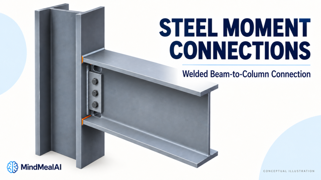
A beam-to-column detail can contain several plates, bolts, and welds, but the key question is simple: does the joint mainly transfer shear, or must it also transfer bending moment?
Steel moment connections are designed to transfer bending between members with the rotational behavior assumed in the structural analysis. Understanding that behavior helps engineers and drafters see why flange attachments, column reinforcement, and connection dimensions cannot be treated as isolated details.
1. Moment Connection vs Simple Shear Connection
A simple beam connection accommodates the beam-end rotation assumed in the analysis while carrying its specified forces. A moment connection deliberately transfers bending between the connected members.
| Question | Simple connection | Moment connection |
|---|---|---|
| How is beam-end bending treated? | Moment resistance is neglected in the usual simple-frame idealization. | Moment transfer is included in the joint design and frame analysis. |
| What rotation behavior is needed? | Enough flexibility and rotation capacity for the assumed beam behavior. | Rotational stiffness and capacity consistent with the frame model. |
| Where might forces transfer? | Often through a beam-web attachment. | Often through flange-level force paths plus a shear-transfer path. |
A simple connection is not literally free of every local moment. Eccentricity can create bending within its bolts, plate, or welds. Similarly, adding more bolts to a shear tab does not automatically turn it into a moment connection.
2. How a Beam Transfers Bending Moment
One useful teaching model replaces the bending moment with two equal and opposite forces separated by a distance. This is a force couple. In a flange-couple idealization, one beam flange is in tension and the other is in compression.
A moment can be represented by a force couple
The approximate relationship is F = M / z, where M is the moment and z is the distance between the assumed force resultants. For a simplified flange-only model, z is commonly taken between the flange centroids, not automatically as the overall beam depth.
Suppose the moment is 120 kip-ft and the assumed lever arm is 24 in., or 2 ft:
If the same moment acts with a 20-inch lever arm, the force becomes 72 kips. This explains why changing beam depth can affect a connection even when the required moment remains unchanged.
This example is not a bolt or weld design. Real force distribution depends on connection geometry, stiffness, axial load, the contribution of the web, and the chosen design method. Vertical shear still needs its own valid load path.
3. “Moment-Resisting” Does Not Always Mean Perfectly Rigid
Connection strength and stiffness answer different questions. Strength concerns how much force or moment the joint can resist. Stiffness concerns how much it rotates as the moment increases.
| Behavior | Meaning for the frame model |
|---|---|
| Fully restrained (FR) | Relative rotation between connected members is small enough to neglect for the intended analysis. |
| Partially restrained (PR) | The connection transfers moment, but its relative rotation must be represented in the analysis. |
FR does not mean the joint undergoes absolutely no deformation. Nor does the FR label alone mean that the connection develops the full strength of every attached member. The required behavior and strength must both be established.
4. Common Ways to Create a Moment Connection
- Welded flange connections: beam flange forces transfer through designed welds to the supporting member. The web connection and access details must suit the selected system.
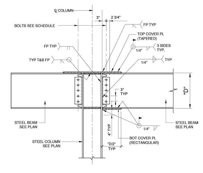
- Bolted flange-plate connections: plates provide flange-level force paths, with bolts and welds forming the complete transfer mechanism.
- Bolted end-plate connections: a plate welded to the beam end connects to the column. Tension-side bolt forces, plate bending, and compression-side bearing work together.
- Reduced beam section (RBS) connections: controlled cuts in the beam flanges create an intended yielding region away from the column face. The beam-to-column joint still needs the specified connection details.
These names describe connection families. A similar-looking detail is not necessarily equivalent, and an RBS cut is not something to add to an ordinary connection without a complete design.
5. The Column Must Receive the Flange Forces
The load path does not stop at the beam-end weld or bolt. The column flange and web must receive and distribute the connection forces.
The column is part of the connection
zone
(if required)
Continuity plates are transverse reinforcing plates within the column, commonly located near beam-flange levels. They help transfer concentrated forces where required by the applicable checks and connection provisions.
The panel zone is the column-web region within the joint between the beam-flange levels. It participates in the joint’s shear response. A doubler plate, when required, reinforces the web region; it is not the same component as a continuity plate.
Not every moment connection needs both forms of reinforcement. The engineer checks the column, joint forces, and applicable connection requirements. A heavier column can sometimes be a more practical choice than adding several reinforcing plates and welds.
6. Seismic Moment Connections Need More Than a Static Strength Check
A connection in a seismic moment frame may experience repeated moment reversals and substantial inelastic rotation. A joint that resists one static load is not automatically suitable for that duty.
For U.S. projects, AISC 341 provides seismic provisions, while AISC 358 covers prequalified connections for special and intermediate steel moment frames. A prequalified connection must remain within its stated limits and satisfy its detailing requirements.
Those limits can include member sizes, materials, geometry, weld details, and other restrictions. When a protected zone is specified, attachments or modifications in that zone require attention to the applicable requirements. Do not treat a published sketch as a universally approved detail.
This guide references ANSI/AISC 358-22 for connection-family context. The project’s governing code and referenced standard editions determine which provisions apply.
7. Practical Drawing Checks Before Issuing the Detail
- Confirm the intended connection behavior. The detail should agree with the analysis assumptions, required moment, shear, axial force, and any reversal requirements. Keep LRFD and ASD demands clearly identified.
- Check member orientation. A detail for a beam framing into a column flange cannot simply be reused for a column-web connection.
- Follow the flange force paths. Confirm the plates, bolts, welds, and supporting material that carry tension and compression.
- Keep the shear path explicit. Do not assume flange attachments alone resolve the beam-web connection.
- Coordinate reinforcement and access. Check continuity plates, any doubler plates, bolt clearances, welding access, and the fabrication sequence.
- Respect the selected connection system. Changes to beam setback, plate thickness, bolt layout, access holes, or RBS geometry may change its behavior or qualification.
A useful review question is: “If the moment reverses, can I still follow a complete load path?” That question often reveals assumptions hidden behind a familiar-looking detail.
Frequently Asked Questions
Are all welded beam connections moment connections?
No. Welding is a fastening method. A welded web attachment may still form part of a simple connection. Classification depends on the designed force transfer and rotational behavior.
Can a bolted connection transfer moment?
Yes. Bolted flange-plate and end-plate systems are examples. Their plates, bolts, welds, and supporting members must be designed together.
Does a moment connection eliminate the need for bracing?
No. The frame’s lateral-force-resisting system and the members’ stability restraints are separate design questions. Individual beams may still need lateral bracing.
What to Remember
A moment connection is a designed load path with a defined rotational response. Start with the required actions, follow the force paths into the column, and make sure the drawing matches the structural model and selected connection system.
Related reading: Steel Connection Design: How Forces Travel Through Bolts, Welds, and Plates and When Do Steel Beams Need Web Stiffeners?.
Technical References
- AISC, Specification for Structural Steel Buildings: connection behavior and concentrated-force provisions.
- ANSI/AISC 341-22, Seismic Provisions for Structural Steel Buildings.
- ANSI/AISC 358-22, Prequalified Connections for Special and Intermediate Steel Moment Frames for Seismic Applications.
- AISC Engineering Journal, Panel Zone Yielding in Steel Moment Connections.
- Steel Construction Institute / SteelConstruction.info, Moment-resisting connections: conceptual end-plate behavior. Eurocode design equations are not used here.
Educational explanation of steel building connections. Figures are conceptual and the numerical example is a force-couple calculation, not a completed connection design.
MindCore