Shear Tab Connection: Load Path, Bolts, Welds and Drawing Checks
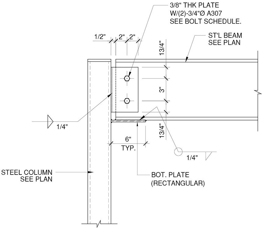
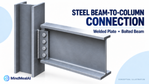
A shear tab connection connects a steel beam web to a supporting column or girder through a single steel plate. In the common arrangement, the plate is welded to the support and bolted to the beam web. The connection transfers the beam-end shear reaction while accommodating the rotation associated with a simple beam.
This guide explains the connection, its load path and the drawing checks that help prevent coordination errors. It uses U.S. AISC terminology; projects outside the United States must follow their governing standards.
What is welded, and what is bolted?
| Component | Connection | What to check |
|---|---|---|
| Shear plate to column or girder | Commonly shop welded | Weld size, length, sides and supporting material |
| Beam web to shear plate | Commonly field bolted | Bolt specification, holes, spacing and installation requirements |
| Beam flanges at the support | Not connected for moment transfer in this illustrated detail | End clearance and whether a separate moment detail is required |
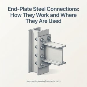
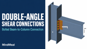
For a beam framing to a column flange, the shear plate projects outward from the flange and overlaps one side of the beam web. The bolts pass through both pieces. The plate is not a horizontal seat beneath the beam. Shop welding and field bolting are common fabrication choices; the approved drawings determine the actual arrangement.
How the load reaches the column
Follow the connection from the supported member toward the support: beam web, bolted joint, shear plate, weld, then column or girder. Each interface must transfer the required force. A strong plate cannot compensate for an inadequate weld, weak beam web or unsuitable supporting wall.
At a bearing-type bolted joint, load transfer involves bolt shear and bearing at the holes as the joint engages. A slip-critical joint additionally requires resistance to slip at the specified design condition through the clamped faying surfaces. The words “high-strength bolts” alone do not identify the joint category or surface preparation.
Is a shear tab a pinned connection?
A shear tab is commonly used where the structural model assumes a simple beam connection. That does not mean the real connection has absolutely zero stiffness or zero local moment. It must accommodate the required beam-end rotation, and the connection design must address the effects of its geometry.
The distance between the weld and bolt line creates an eccentric load-transfer problem. The effective eccentricity used in design depends on the applicable method and configuration; it should not be chosen by appearance. Similarly, increasing plate thickness is not automatically an improvement: strength and rotational behavior must work together.
Conventional versus extended shear tabs
| Configuration | Practical distinction | Design implication |
|---|---|---|
| Conventional single-plate connection | Compact geometry within the limits of the applicable procedure | Verify all geometric, material and hole-type restrictions before using tabulated strengths |
| Extended single-plate connection | Plate projects farther or uses geometry outside conventional limits | Use the applicable extended procedure; plate stability and eccentricity deserve particular attention |
An extended plate can help move the bolted connection clear of an obstructing support. It is not simply a conventional tab made longer. Older technical articles explain how these procedures developed, but their historical bolt strengths and dimensional limits should not be copied into a current project without checking the governing edition.
What controls the connection strength?
| Check | Why it matters |
|---|---|
| Bolts and bolt group | Bolt shear strength and the distribution of forces must suit the design model |
| Bearing and tearout | Both the plate and beam web can govern around bolt holes |
| Plate and beam-web sections | Shear yielding, rupture and block shear can limit the available strength |
| Plate bending and stability | Projecting geometry may require additional checks under the selected procedure |
| Weld and base metal | The attachment must deliver the required force into the support |
| Supporting member | A column flange, girder web or HSS wall can require its own local checks |
| Rotation and fit | A connection must fit physically and behave consistently with the structural model |
For example, adding another bolt does not guarantee a proportional increase in connection capacity. A plate edge, weld or supporting member may already control. The same bolt arrangement can also behave differently when attached to a thin HSS wall instead of a wide-flange column flange.
A practical drawing-review checklist
Start with the connection mark on the framing plan and trace it to the detail and schedule. Check the following items together, rather than reviewing each drawing in isolation:
1. Design basis. Confirm the reaction, any axial or other specified forces, and whether values are LRFD or ASD. Do not mix factored loads with allowable strengths.
2. Member orientation. Confirm the support face, beam side, skew and elevations. A connection to a column web may have different access restrictions from one to a flange.
3. Plate definition. Show thickness, height, projection, material and position relative to the beam. Match the plate mark to the schedule.
4. Bolts and holes. Identify bolt diameter and specification, number, hole type, slot direction where used, spacing and edge distances. Check both connected pieces.
5. Weld definition. Show the required weld size, effective length and applicable sides. Coordinate welding access and the support material.
6. Clearances. Check beam setback, flange and root-fillet interference, erection space, bolt insertion and wrench access. A modeled bolt is not proof that a wrench will fit.
7. Copes and supports. Where a cope is necessary, coordinate its dimensions and the resulting beam-end checks. Review any support reinforcement or HSS-specific detail.
8. Document consistency. Reconcile the plan, section, schedule and model. Record unresolved differences as questions for the responsible designer.
Common questions
Can I weld the beam flanges to make it stronger?
Adding flange welds changes the connection behavior and force path. If moment transfer is required, it needs an appropriate designed detail rather than an improvised addition to a shear tab.
Are slotted holes always acceptable?
No. Hole type, slot orientation, washers and installation requirements must agree with the design and governing bolting provisions. Slots should not be introduced solely to resolve a fit-up problem without review.
Is there a universal plate thickness or bolt count?
No. Those choices depend on the required forces, materials, geometry, support and design procedure. The schematic above intentionally provides no construction dimensions.
Reference basis and scope
Reference framework: ANSI/AISC 360-22, Specification for Structural Steel Buildings; AISC Steel Construction Manual, 16th Edition, Part 10, Design of Simple Shear Connections; and RCSC Specification for Structural Joints Using High-Strength Bolts, June 5, 2025. The 2025 RCSC publication supersedes its 2020 publication, but the edition adopted for a project must be established from its governing code and contract documents.
Technical background: Muir and Thornton (2011), “The Development of a New Design Procedure for Conventional Single-Plate Shear Connections,” AISC Engineering Journal; Muir and Hewitt (2009), “Design of Unstiffened Extended Single-Plate Shear Connections,” AISC Engineering Journal. These historical papers explain connection behavior and procedure development, rather than supplying current project design values.
MindCore