Anchor Rods in Steel Structures: Tension, Shear, and Failure Modes
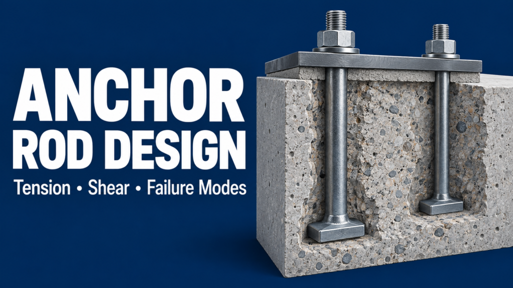
Anchor rod design is an essential part of connecting a steel structure to its concrete foundation. Anchor rods can resist uplift, moment-related tension, and shear when the connection is designed to transfer those forces through the rods.
However, a strong steel rod does not guarantee a strong anchorage. The concrete, embedment, edge distances, base plate, and installation details all influence the available strength. This guide explains tension, shear, and the main failure modes without turning the discussion into a calculation manual.
What Are Anchor Rods?
Anchor rods connect steel components, such as column base plates, to concrete. The term “anchor bolt” is also common, but AISC uses “anchor rod” to distinguish foundation anchorage from bolts used in steel-to-steel connections.
This article focuses mainly on column-base anchorage. Cast-in rods are positioned before concrete placement. Post-installed anchors are installed in hardened concrete and must follow the requirements for the selected anchor system. They are not interchangeable simply because their diameters match.
1. Anchor Rods in Tension
Tension develops when the connection pulls upward on an anchor. This can occur under uplift or when overturning moment causes one side of a base plate to lift while the opposite side bears against the support.
The load travels from the steel member into the base plate and connection hardware, through the rod, and into its concrete anchorage. Every part of that path needs adequate strength.
Do not automatically divide the total force equally among all rods. The loading, anchor layout, plate stiffness, and contact with the support affect the tension distribution. Plate flexibility can also introduce prying effects where applicable.
2. Anchor Rods in Shear
Shear acts across the rod rather than along its length. At a column base, horizontal load may be transferred through friction, a designed anchor-rod mechanism, a shear lug, or another specified arrangement.
First identify which mechanism the design uses. The presence of anchor rods does not mean that they are intended to carry all base shear.
When rods do transfer shear, hole clearance and the washer or plate arrangement influence how the load reaches them. Depending on the detail, rods can experience bending as well as shear. Grout thickness and any unsupported length are therefore relevant to the connection behavior.
If tension and shear occur together, check their interaction using the applicable design provisions. Passing separate tension-only and shear-only checks is not always sufficient.
3. Common Anchor Failure Modes
The following terms describe different physical behaviors. The applicable checks depend on anchor type, geometry, loading, and the governing specification.
| Failure mode | What happens | Typical concern |
|---|---|---|
| Steel failure | The rod’s steel resistance is exceeded in tension, shear, or combined action. | Rod material, effective steel area, and loading. |
| Concrete breakout in tension | A region of concrete separates around an anchor or anchor group. | Embedment, edges, spacing, and concrete condition. |
| Pullout | The anchor loses its local anchorage, such as through bearing failure around an embedded head. | The anchoring mechanism and its bearing or engagement. |
| Side-face blowout | Concrete breaks out at a side face near the bearing region of certain deeply embedded headed anchors. | Head location relative to nearby concrete edges. |
| Concrete edge breakout in shear | Shear loading breaks a region of concrete toward an edge. | Edge distance and load direction. |
| Concrete pryout | Shear loading produces a concrete breakout mechanism associated with anchor rotation. | Anchor geometry, embedment, and shear demand. |
| Adhesive bond failure | An adhesive anchor’s bond cannot transfer the required force. | Qualified product data and installation conditions. |
Concrete pryout is different from base plate prying action. Pryout is a concrete failure mode; plate prying concerns additional anchor tension that can arise from connection deformation.
4. Why Embedment, Spacing, and Edge Distance Matter
Effective embedment is a design dimension associated with the anchor’s load-transfer mechanism. It is not necessarily the same as the rod’s total length below the concrete surface. Use the definition for the selected anchor type.
Spacing matters because nearby anchors can have overlapping concrete breakout regions. A group should not automatically be assigned the sum of isolated-anchor capacities.
Concrete edge distance affects the available concrete around the anchorage. It is separate from the distance between the rod and the edge of the steel base plate.
Concrete cracking, member thickness, and reinforcement also influence the design. Nearby reinforcement should only be credited as anchor reinforcement when it is designed and detailed to develop the required forces.
5. Specify the Material, Not Just the Diameter
ASTM F1554 is a common specification for foundation anchor rods. Its Grades 36, 55, and 105 identify minimum yield-strength levels in ksi—not an allowable load for the completed anchorage.
A drawing that lists only a diameter leaves important material information unresolved. Specify the required grade and coordinate the compatible nuts, washers, finish, and other hardware.
Weldability also needs attention. F1554 Grade 55 is not automatically weldable; supplementary requirement S1 addresses weldability when specified. Do not assume that an anchor rod can be welded as a field repair merely because it is steel. Any repair must be reviewed for the actual material and connection.
6. Installation Is Part of the Design
For cast-in rods, coordinate the setting template, orientation, embedment, top projection, and surrounding reinforcement before the concrete is placed. Check the setting plan against the steel base plate detail.
For post-installed anchors, use the selected product’s approved installation requirements. These can address drilling, hole cleaning, installation torque, concrete conditions, and adhesive curing. A generic note such as “epoxy anchor” does not identify a complete anchoring system.
Do not apply steel-to-steel bolt pretension procedures to anchor rods by default. Tightening and installation requirements must match the specified anchorage detail.
Practical Example: Why a Larger Rod May Not Solve the Problem
Imagine a column base close to a concrete pedestal edge. The rod’s steel tension strength is adequate, but the concrete breakout check governs.
Changing to a higher-strength rod does not create more concrete around the anchorage. Possible design changes might involve the layout, pedestal geometry, embedment, or properly designed anchor reinforcement. Each alternative requires evaluation; none is a universal fix.
The useful question is therefore: Which failure mode controls, and what change addresses that mechanism?
Anchor Rod Drawing Review Checklist
- Identification: Quantity, diameter, material specification, grade, and anchor type.
- Plan layout: Dimensions from column centerlines, orientation, and spacing.
- Vertical dimensions: Required embedment, total length, and top projection, with clear reference elevations.
- Hardware: Nuts, washers, plate washers where required, and thread requirements.
- Concrete coordination: Pedestal dimensions, concrete edge distances, and reinforcement conflicts.
- Base plate coordination: Hole sizes, grout thickness, leveling arrangement, and tool access.
A rod that is correctly located in plan can still be too short above the concrete. Check that the projection accommodates the specified grout, plate, washers, nuts, and required thread engagement.
Frequently Asked Questions
Are anchor rods and structural bolts the same?
No. They serve different connection applications. Material, installation, hole, and tightening requirements should be selected for the actual use.
Do all anchor rods resist shear?
No. The intended base shear-transfer mechanism must be identified. Rods require the appropriate checks and detailing when they are assigned shear.
Is deeper embedment always sufficient?
No. Embedment is only one factor. Concrete geometry, edges, anchor-group effects, steel strength, and the specific anchoring mechanism may still govern.
Key Takeaways
Anchor rod design must address both steel and concrete behavior. Identify the tension and shear demands, check the applicable failure modes, and coordinate the installation details. A complete anchorage specification communicates how the connection works as well as what size rod to install.
This article explains general concepts. Project-specific design must follow the governing AISC and ACI provisions, applicable seismic requirements, and product-specific requirements where relevant.
Related Articles
- Steel Base Plate Design: Bearing, Anchor Rods, and Load Transfer Explained
- HSS Connection Design: Common Challenges Engineers Need to Consider
Technical References
AISC, Design Guide 1: Base Connection Design for Steel Structures, third edition (2024); AISC Engineering FAQs, Anchor Rods, Base Plates, and Embedded Plates; ACI 318, Chapter 17, in the governing edition; ASTM F1554, applicable specified edition; Hilti, technical resources on anchor load-transfer mechanisms and failure modes; Portland Bolt, ASTM F1554 and Weldable F1554-55 Anchor Bolts; AISC Engineering Journal, Experimental Investigation of Shear Transfer in Exposed Column Base Connections.
MindCore