Steel Base Plate Design: Bearing, Anchor Rods, and Load Transfer Explained
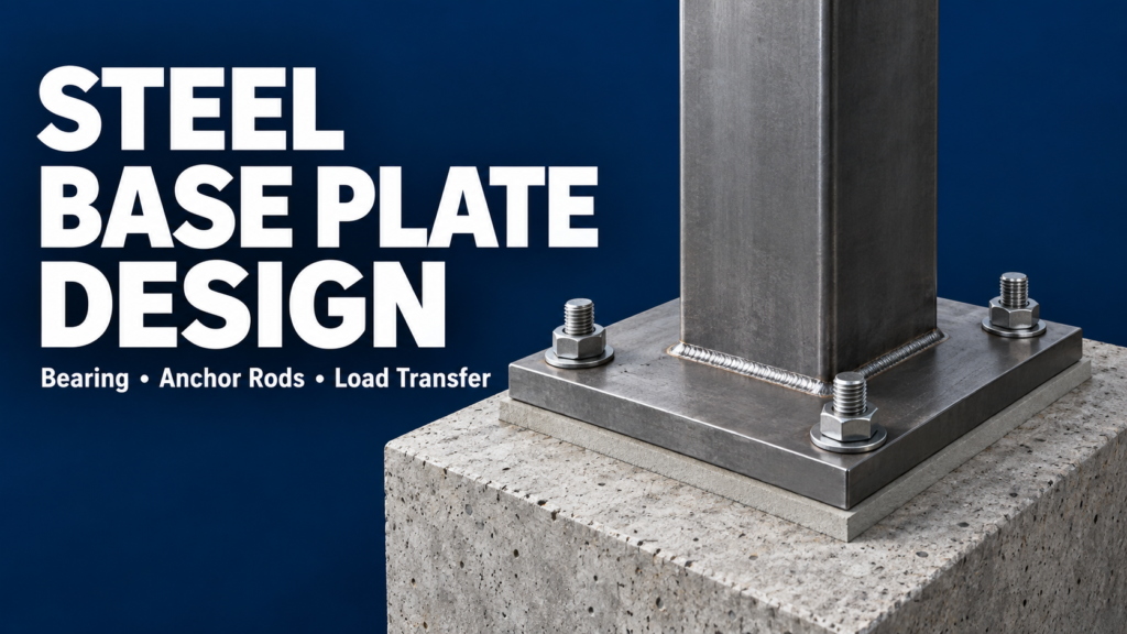
Steel base plate design connects the behavior of a steel column to the concrete foundation below it. The plate spreads compression over a bearing area, while anchor rods and other connection components transfer the forces assigned to them by the design.
A base plate may look simple on a drawing, but its dimensions, thickness, welds, grout, and anchor layout must work together. This guide explains the load paths and the practical details that engineers and structural detailers need to coordinate.
What Is a Steel Base Plate?
A base plate is a steel plate at the bottom of a column that connects it to its support. In a typical grouted exposed base, the assembly includes the column, column-to-plate connection, base plate, anchor rods with nuts and washers, grout, and concrete pedestal or footing.
It differs from a cap plate. A cap plate sits at the top of a column and may support a beam; a base plate sits at the bottom and transfers forces into the foundation.
1. Understand the Base Connection Load Paths
| Action | Typical load-transfer behavior |
|---|---|
| Compression | Column forces pass into the plate, through the grout bearing layer, and into the supporting concrete. |
| Uplift or tension | The column-to-plate connection and plate transfer tension to the anchor rods and their anchorage in concrete. |
| Moment | Bearing pressure becomes uneven; depending on the axial load and moment, part of the plate may lift and anchors may develop tension. |
| Shear | A specified mechanism—such as friction, designed anchor rod action, or a shear lug—transfers the horizontal force. |
The applicable load combinations matter. A base under substantial compression in one case may experience reduced compression or uplift in another. Its load path must remain adequate for each required condition.
2. Base Plate Area and Thickness Serve Different Purposes
Plate area helps distribute compression to the supporting concrete. The required bearing area depends on the force and the applicable concrete bearing strength, including the actual support geometry.
Plate thickness provides resistance to plate bending. Portions extending beyond the column can bend under bearing pressure. Anchor tension can produce another plate-bending condition.
A wider plate is therefore not automatically a better solution. It may reduce bearing pressure while increasing the projection beyond the column and changing the bending demand. The plate plan dimensions and thickness should be evaluated together.
HSS and wide-flange columns also have different footprints. Their plate-bending assumptions and effective load-transfer regions should match the column shape rather than being copied without review.
3. Anchor Rod Design Includes the Concrete
Anchor rods provide a positive connection between the steel base and the foundation. Their size and arrangement depend on the forces they are required to resist, including uplift and moment-related tension where applicable.
Checking the steel rod alone is insufficient. Depending on the anchor type and loading, anchorage checks can include concrete breakout, pullout, side-face blowout, pryout, and combined tension and shear. Not every failure mode applies to every anchor.
Embedment, spacing, distance to concrete edges, concrete condition, and the surrounding reinforcement can affect performance. A larger rod does not necessarily solve a connection governed by concrete failure.
Keep two dimensions distinct: distance from a rod to the steel plate edge and distance from a rod to the concrete edge. They address different checks and should both be coordinated.
4. Specify How Shear Reaches the Foundation
Do not assume that the anchor rods resist all horizontal force simply because they pass through the base plate. Base connections can use different shear-transfer mechanisms, and each requires appropriate design and detailing.
- Friction: Requires an applicable design basis and sufficient compression for the load combination being checked.
- Anchor rod action: Requires checks of the rods, concrete anchorage, and the details that engage the rods, including the plate-hole arrangement.
- Shear lug: A projection below the plate can transfer shear by bearing into a designed supporting region. The lug, welds, grout pocket, and concrete require coordination.
Clearance in oversized holes can influence when rods engage in shear. Do not assume that friction, anchor rods, and a shear lug automatically share the force or that their capacities can simply be added.
5. Grout and Installation Details Matter
Grout fills the space between the base plate and the concrete support to establish the intended bearing interface. Voids beneath a plate can leave a different support condition from the one assumed in design.
Coordinate the grout specification and thickness, leveling method, anchor projection, nut and washer arrangement, and installation sequence. The space available must accommodate the plate and hardware as well as the required leveling adjustment.
The erection condition may differ from the completed grouted condition. Temporary support and stability requirements should be resolved before the column is released from erection equipment.
6. Keep the Detail Consistent with the Structural Model
A base with several anchor rods is not automatically a fixed base. Its rotational behavior depends on the plate, anchors, column connection, concrete support, and their interaction.
The connection must provide the strength and behavior required by the structural analysis. A detail intended mainly for gravity support should not be reused as a moment-resisting base without the appropriate evaluation.
Column-to-plate welds must also match the intended load transfer. An all-around weld symbol does not establish capacity by itself, and weld size should not be selected solely from the plate thickness.
Practical Example: One Column, Two Loading Conditions
Consider the same HSS column in two situations. With predominantly concentric compression, the designer focuses on the bearing area, plate bending, and the other applicable connection requirements.
Now add overturning moment and possible uplift. Bearing may act over only part of the plate, anchor tension becomes important, and the plate must transfer forces between the column, bearing region, and anchors.
The column designation may be unchanged, but the required base detail can be different. This is why a base plate should not be chosen from column size alone.
Base Plate Drawing Review Checklist
- Plate: Plan dimensions, thickness, material, orientation, and column position.
- Anchor rods: Quantity, diameter, grade, layout, embedment, and projection.
- Holes and hardware: Hole sizes, nuts, washers, and any specified plate washers.
- Concrete: Pedestal dimensions, edge distances, and reinforcement coordination.
- Grout and elevations: Grout thickness, leveling arrangement, and clearly identified elevation references.
- Connections: Weld requirements and any shear lug, stiffener, or other designed component.
A useful coordination check is to compare the anchor setting plan with the steel base plate detail. Confirm that rod locations, orientation, and projections agree before concrete placement.
Frequently Asked Questions
Is a base plate the same as a cap plate?
No. A base plate connects the bottom of a column to its support. A cap plate is located at the top of the column, such as beneath a supported steel beam.
Does making the plate thicker solve every problem?
No. It can improve plate-bending resistance, but it does not automatically correct insufficient concrete bearing strength, inadequate anchorage, or an unresolved shear load path.
Can I choose a base plate from a standard size table?
A standard detail can be a starting point if its design conditions are known. Column size alone does not establish the required plate, anchors, or foundation capacity.
Key Takeaways
Start with the forces and the intended load paths. Check plate bearing and bending separately, evaluate the anchor system together with its concrete support, and specify how shear is transferred. Then make sure the drawings provide enough information to build the connection as designed.
This is a conceptual guide, not a project-specific design procedure. Use the governing editions of the steel and concrete specifications; seismic applications can require additional provisions.
Related Articles
- HSS Connection Design: Common Challenges Engineers Need to Consider
- Steel Connection Design: How Forces Travel Through Bolts, Welds, and Plates
Technical References
AISC, Design Guide 1: Base Connection Design for Steel Structures, third edition (2024); AISC Engineering FAQs, Anchor Rods, Base Plates, and Embedded Plates; Steel Tube Institute, HSS Base Plate Design for Axial Compression and Bending Moment and Axially Loaded HSS Column to Base Plate Connections; ACI 318, Chapter 17, anchoring-to-concrete provisions in the governing edition; AISC Engineering Journal, Experimental Investigation of Shear Transfer in Exposed Column Base Connections. Older reference articles may cite earlier code editions.
MindCore