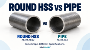
HSS Connection Design: Common Challenges Engineers Need to Consider
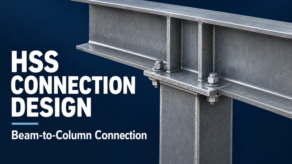
HSS connection design requires more than checking bolts and welds. Hollow structural sections have a closed shape, so engineers must also consider how concentrated forces enter the tube wall and whether the connection can be fabricated, assembled, and inspected.
A square or rectangular HSS may work well as a column or brace while still needing careful attention at its connections. The key is to consider the member and its connections together, before the section size and wall thickness are finalized.
Quick takeaway: Check the load path, local HSS wall behavior, and installation access. A larger weld alone cannot solve every connection problem.
Why HSS Connections Need Special Attention
With an open steel section, many connection surfaces are accessible from both sides. An HSS encloses its interior, which changes how bolts, backing, internal plates, and tools can be installed.
The tube wall also has to receive the connection forces. A plate welded to one face can place a concentrated demand on a relatively small area. The entire HSS cross-section does not necessarily participate equally at that location.
These two questions provide a useful starting point: Where does the force go, and how will the connection be built?
1. Establish the Load Path Before Choosing the Detail
Begin with the forces that the connection must transfer: shear, tension, compression, moment, or a combination. Then follow those forces through the connected member, fasteners, plates, and supporting HSS.
A beam shear connection and a moment connection may look similar in a small drawing, but they serve different purposes. A moment connection must transfer a force couple and provide behavior consistent with the structural model. A shear connection must accommodate the required beam-end rotation.
Show offsets as well as member centerlines. When the force acts away from the connection’s resisting elements, the resulting eccentricity can add demands that a centered sketch would hide.
2. Check the HSS Wall, Not Just the Attachment
The face-loading behaviors below concern applicable side-connected plates or branches. The cap-plate bearing example later in this article has a different load path and requires checks appropriate to that arrangement.
A strong plate or weld does not guarantee that the supporting tube wall is adequate. Depending on the connection geometry and loading, local checks may include:
| Potential limit state | Plain-language meaning |
|---|---|
| Face plastification | The connected HSS face bends and yields locally under a concentrated force. |
| Punching shear | Shear demand develops around the loaded region of the tube wall. |
| Sidewall yielding or local instability | The sidewalls supporting the loaded face yield or become locally unstable. |
| Local yielding of the attached element | The load is concentrated in an effective portion of a plate or branch, rather than distributed evenly across its full width. |
These are possible behaviors, not a checklist that applies identically to every HSS connection. Engineers must select the checks and geometric limits that match the actual connection type.
Also confirm the design wall thickness used in the calculations. Depending on the material specification and applicable design provisions, it may differ from the nominal thickness in the member designation.
3. Plan Bolt Access Early
Conventional bolts generally need access to both the head and the nut during installation. That access may be unavailable once an HSS end is closed or another member is in place.
Possible approaches include externally accessible connection plates, access openings where structurally acceptable, through-bolts, or suitable blind structural fasteners. Each option changes the detailing and design checks.
Through-bolts should not be treated as an automatic solution: the HSS walls and the intended tightening condition need evaluation. Blind fasteners must be selected using the applicable product requirements and supporting design information, including hole size, grip range, and installation access.
Detailing question: Can the installer actually reach the fastener with the required tool after the surrounding steel is erected?
4. Match the Weld Detail to the HSS Geometry
HSS corners, wall flexibility, and the position of an attached plate affect the weld detail. The designer should verify that the specified weld can be made with the available access and joint preparation.
For some welded HSS connections, the effective weld length used in design is less than the full visible weld length because force transfer is not uniform. Do not assume that every segment of an all-around weld carries an equal share of the load.
The drawing should clearly distinguish weld type, size, extent, and shop or field location. Increasing weld size should follow a design check of both the weld and the connected base metal.
5. Consider Reinforcement Without Making It the Default
If the HSS wall cannot resist the connection demand, an engineer may consider a different load-transfer arrangement, reinforcement, or a different HSS section. Through-plates, diaphragms, and external plates are possible strategies, but their effectiveness depends on the specific detail.
Reinforcement also adds fabrication work. Internal components may have to be installed before the tube is closed, while through-plates can require slots, additional welds, and careful fit-up.
In some cases, choosing a thicker HSS wall early can simplify the connection enough to offset the additional member weight. Compare the complete fabricated connection—not only the weight of the tube.
A through-plate is not required for every beam shear connection to an HSS column. A face-welded single plate may be suitable when the applicable member, connection, and local wall checks are satisfied.
6. Coordinate Fabrication and Erection
A connection should have a workable assembly sequence. Before releasing the detail, consider when each plate, bolt, and weld becomes accessible—and when it becomes inaccessible.
- Shop versus field work: Identify which pieces arrive attached and which are installed on site.
- Fit-up: Coordinate slots, plate locations, member ends, and realistic fabrication tolerances.
- Tool clearance: Check access for tightening bolts and making the required welds.
- Inspection: Avoid leaving critical work concealed before the required inspection can occur.
These questions are especially useful when several beams or braces connect near the same HSS corner. A detail that works by itself may conflict with an adjacent plate or fastener.
Practical Example: A Steel Beam Bearing on an HSS Column
This example follows the author’s beam-to-column detail. A steel wide-flange beam bears on a cap plate at the top of an HSS column. Bolts connect the beam’s bottom flange to the cap plate, and transverse stiffeners are provided on both sides of the beam web at the support.
Detail B shows a beam continuing across the column support, while Detail A shows an end-support arrangement. The bolt layout and cap plate geometry differ between the two conditions.
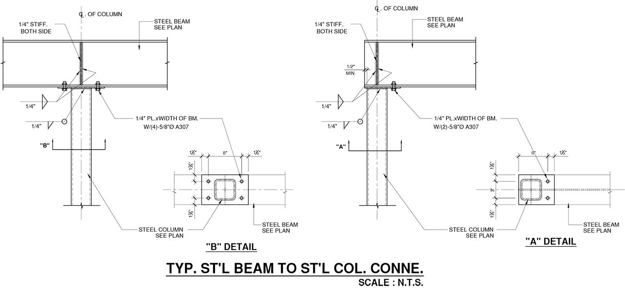
For downward gravity loading, the beam reaction is transferred by bearing through the cap plate into the HSS column. The bolts and welds must also be checked for the forces assigned to them by the design, including uplift or horizontal forces where applicable. The detail should not be assumed to provide a moment connection solely because bolts and stiffeners are present.
The engineer evaluates the beam’s local behavior at the support, stiffeners and their welds, cap plate behavior, applicable HSS column checks, and the required bolt and weld strengths. The detailer confirms bolt access, plate projections, stiffener position, and clearances. The member sizes, plate thicknesses, bolt specifications, and weld sizes shown in the drawing are project-specific.
HSS Connection Drawing Review Checklist
Before a detail is issued, confirm that the drawings communicate:
- The complete HSS size, material specification, and member orientation.
- The connection’s design intent and required forces where specified by the project’s design-responsibility arrangement.
- Plate dimensions, locations, and material requirements.
- Bolt and hole requirements, spacing, edge distances, and installation access.
- Weld requirements and shop-versus-field locations.
- Any reinforcement, access openings, and critical assembly requirements.
This review helps identify missing information; it does not replace the engineer’s connection calculations.
Frequently Asked Questions
Are welded connections always better than bolted HSS connections?
No. The appropriate choice depends on force transfer, access, fabrication, and erection. Shop-welded attachments with accessible field bolts can be practical, but the complete connection still needs design checks.
Can a larger weld fix an inadequate HSS wall?
Not by itself. If local tube-wall behavior governs, strengthening only the weld does not establish adequate capacity for the supporting wall.
Can a standard HSS connection detail be reused?
It can be a starting point, but the loads, wall thickness, geometry, material, and installation conditions must fit the detail’s design assumptions and limits.
Key Takeaways
- Consider HSS member selection and connection design together.
- Follow the force through the entire connection, including the supporting tube wall.
- Resolve bolt, weld, and inspection access before finalizing the detail.
- Compare reinforcement with simpler alternatives, including a thicker HSS wall.
This article explains general connection concepts. Project-specific design must follow the governing specifications and the responsible engineer’s requirements; seismic or other special systems may require additional provisions.
Related Articles
- Steel Connection Design: How Forces Travel Through Bolts, Welds, and Plates
- HSS Steel Sizes and Properties Table
Technical References
AISC, Design Guide 24: Hollow Structural Section Connections, second edition (2024); AISC Engineering FAQs, Single-Plate Connections; Steel Tube Institute technical articles, Bolting to HSS Members, Transverse Plate-to-Square/Rectangular HSS Connections, Design of Fillet Welds to Rectangular HSS, and Expert Tips for Cost-Effective HSS Specification and Fabrication.
References are listed for background. Older technical articles may cite earlier specifications; use the editions governing the project for calculations.
MindCore